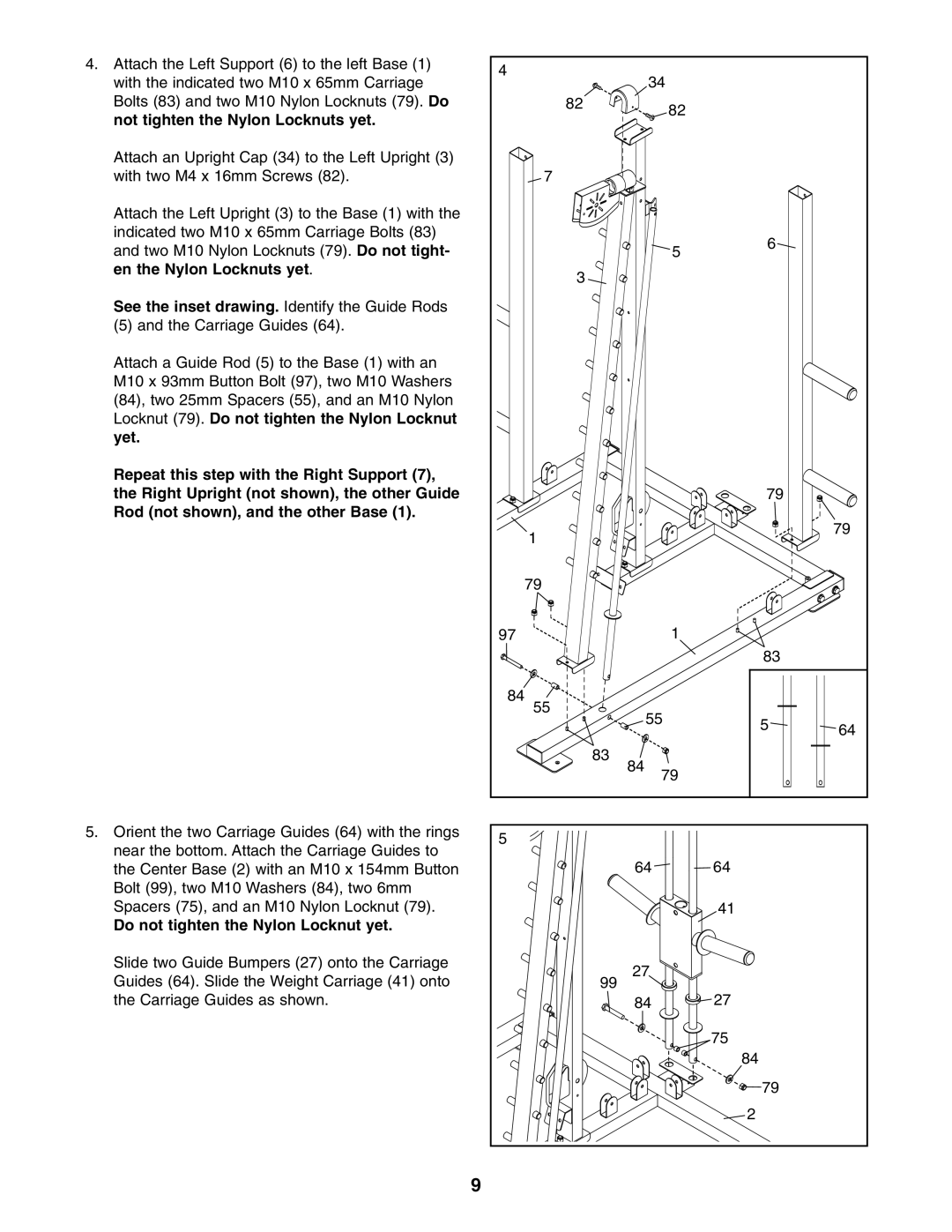
4.Attach the Left Support (6) to the left Base (1) with the indicated two M10 x 65mm Carriage Bolts (83) and two M10 Nylon Locknuts (79). Do not tighten the Nylon Locknuts yet.
Attach an Upright Cap (34) to the Left Upright (3) with two M4 x 16mm Screws (82).
Attach the Left Upright (3) to the Base (1) with the indicated two M10 x 65mm Carriage Bolts (83) and two M10 Nylon Locknuts (79). Do not tight- en the Nylon Locknuts yet.
See the inset drawing. Identify the Guide Rods
(5) and the Carriage Guides (64).
Attach a Guide Rod (5) to the Base (1) with an M10 x 93mm Button Bolt (97), two M10 Washers (84), two 25mm Spacers (55), and an M10 Nylon Locknut (79). Do not tighten the Nylon Locknut yet.
Repeat this step with the Right Support (7), the Right Upright (not shown), the other Guide Rod (not shown), and the other Base (1).
5.Orient the two Carriage Guides (64) with the rings near the bottom. Attach the Carriage Guides to the Center Base (2) with an M10 x 154mm Button Bolt (99), two M10 Washers (84), two 6mm Spacers (75), and an M10 Nylon Locknut (79).
Do not tighten the Nylon Locknut yet.
Slide two Guide Bumpers (27) onto the Carriage Guides (64). Slide the Weight Carriage (41) onto the Carriage Guides as shown.
4 |
|
|
|
|
34 |
|
|
| |
82 |
| 82 |
|
|
|
|
|
| |
7 |
|
|
|
|
|
| 5 | 6 |
|
|
|
|
| |
3 |
|
|
|
|
|
|
| 79 |
|
1 |
|
|
| 79 |
|
|
|
| |
79 |
|
|
|
|
97 |
| 1 |
|
|
|
|
| 83 |
|
84 |
|
|
|
|
55 |
|
|
|
|
55 |
| 5 | 64 | |
|
|
| ||
|
|
|
| |
83 |
|
|
|
|
84 | 79 |
|
| |
|
|
| ||
5 |
|
|
|
|
64 |
|
| 64 |
|
|
|
| 41 |
|
27 |
|
|
|
|
99 |
|
| 27 |
|
84 |
|
|
| |
|
|
| 75 |
|
|
|
| 84 |
|
|
|
| 79 |
|
|
|
| 2 |
|
9