Instructions
GLC 4400 |
|
Lubrication Controller | EN |
| 313855H |
For controlling and monitoring
Part No.: 24B591, Series C: DC Power
Part No.: 24B596, Series C: AC Power
Important Safety Instructions
Read all warnings and instructions in this manual. Save these instructions.
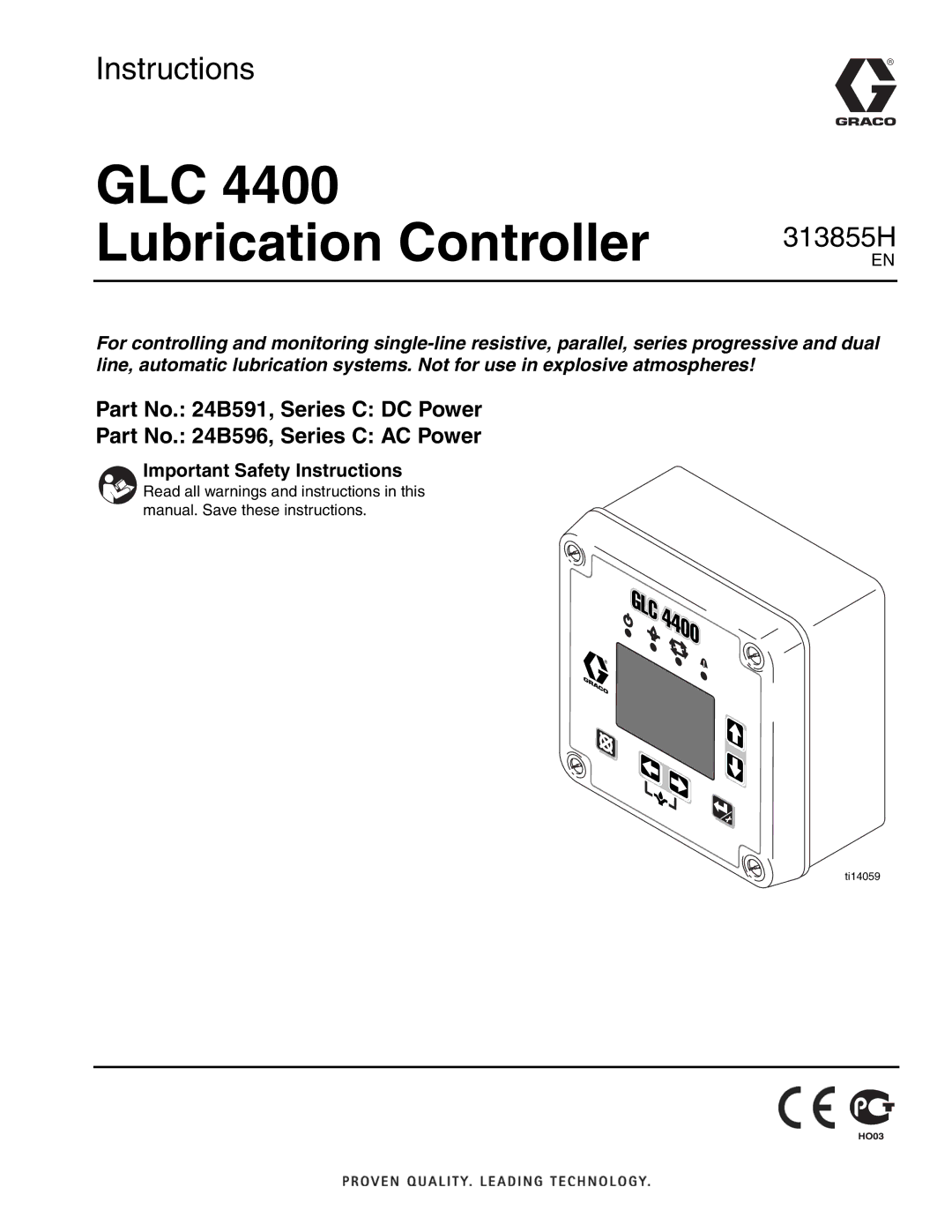
ti14059