Setup
See Electric Connection Warning, page 7.
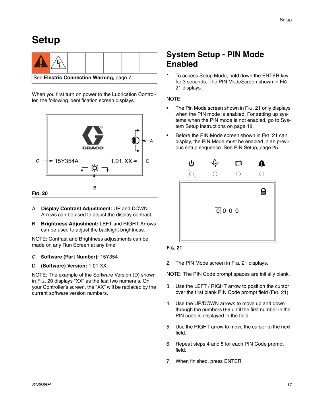
When you first turn on power to the Lubrication Control- ler, the following identification screen displays.
![]() A
A
C ![]()
![]() D
D
B
FIG. 20
ADisplay Contrast Adjustment: UP and DOWN Arrows can be used to adjust the display contrast.
BBrightness Adjustment: LEFT and RIGHT Arrows can be used to adjust the backlight brightness.
NOTE: Contrast and Brightness adjustments can be made on any Run Screen at any time.
CSoftware (Part Number): 15Y354
D(Software) Version: 1.01.XX
NOTE: The example of the Software Version (D) shown in FIG. 20 displays “XX” as the last two numerals. On your Controller’s screen, the “XX” will be replaced by the current software version numbers.
Setup
System Setup - PIN Mode Enabled
1.To access Setup Mode, hold down the ENTER key for 3 seconds. The PIN ModeScreen shown in FIG. 21 displays.
NOTE:
•The Pin Mode screen shown in FIG. 21 only displays when the PIN mode is enabled. For setting up sys- tems when the PIN mode is not enabled, go to Sys- tem Setup instructions on page 18.
•Before the PIN Mode screen shown in FIG. 21 can display, the PIN Mode must be enabled in an previ- ous setup sequence. See PIN Setup, page 25.
FIG. 21
2. The PIN Mode screen in FIG. 21 displays.
NOTE: The PIN Code prompt spaces are initially blank.
3.Use the LEFT / RIGHT arrow to position the cursor over the first blank PIN Code prompt field (FIG. 21).
4.Use the UP/DOWN arrows to move up and down through the numbers
5.Use the RIGHT arrow to move the cursor to the next field.
6.Repeat steps 4 and 5 for each PIN Code prompt field.
7.When finished, press ENTER.
313855H | 17 |