Startup
Startup
Do not operate Reactor without all covers and shrouds in place. Do not attempt to change ratio while machine is pressurized or running. Do not loosen ratio lock handle if A and B component pumps are pressurized or while the pumps are operating.
1.Select ratio
The stroke lengths of the fluid pumps (AA and AB) can be adjusted to select the ratio. The frame (AN) has three pin positions for the bottom of the pump and a slider mechanism at the top of the pump, which allows for positioning of the pump at any required position. This allows for a a range of ratio settings between the first and last settings on the pump drive link.
a.Shutdown system, see page 30.
b.Relieve pressure, see page 31.
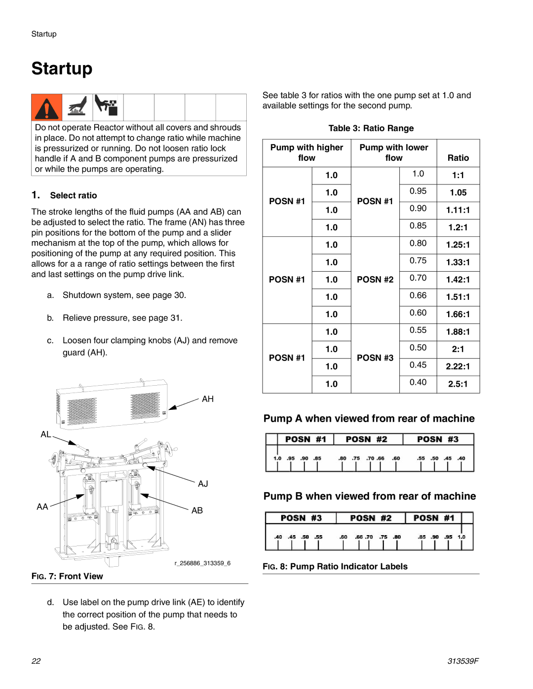
c.Loosen four clamping knobs (AJ) and remove guard (AH).
![]() AH
AH
AL
AJ
AA  AB
AB
r_256886_313359_6
FIG. 7: Front View
d.Use label on the pump drive link (AE) to identify the correct position of the pump that needs to be adjusted. See FIG. 8.
See table 3 for ratios with the one pump set at 1.0 and available settings for the second pump.
Table 3: Ratio Range
Pump with higher | Pump with lower |
| |||
flow |
| flow | Ratio | ||
|
|
|
|
|
|
|
| 1.0 |
| 1.0 | 1:1 |
|
|
|
|
|
|
POSN #1 |
| 1.0 | POSN #1 | 0.95 | 1.05 |
|
|
|
| ||
| 1.0 | 0.90 | 1.11:1 | ||
|
|
| |||
|
|
|
|
|
|
|
| 1.0 |
| 0.85 | 1.2:1 |
|
|
|
|
|
|
|
| 1.0 |
| 0.80 | 1.25:1 |
|
|
|
|
|
|
|
| 1.0 |
| 0.75 | 1.33:1 |
|
|
|
|
|
|
POSN #1 |
| 1.0 | POSN #2 | 0.70 | 1.42:1 |
|
|
|
|
|
|
|
| 1.0 |
| 0.66 | 1.51:1 |
|
|
|
|
|
|
|
| 1.0 |
| 0.60 | 1.66:1 |
|
|
|
|
|
|
|
| 1.0 |
| 0.55 | 1.88:1 |
|
|
|
|
|
|
POSN #1 |
| 1.0 | POSN #3 | 0.50 | 2:1 |
|
|
|
| ||
| 1.0 | 0.45 | 2.22:1 | ||
|
|
| |||
|
|
|
|
|
|
|
| 1.0 |
| 0.40 | 2.5:1 |
|
|
|
|
|
|
Pump A when viewed from rear of machine
Pump B when viewed from rear of machine
FIG. 8: Pump Ratio Indicator Labels
22 | 313539F |