e.Remove base pin (BP) from frame (AN) if the base of the pump needs to be moved. See FIG. 8.
TP
![]() BP
BP
3 | 2 1 | r_256886_313359_7 |
|
FIG. 9
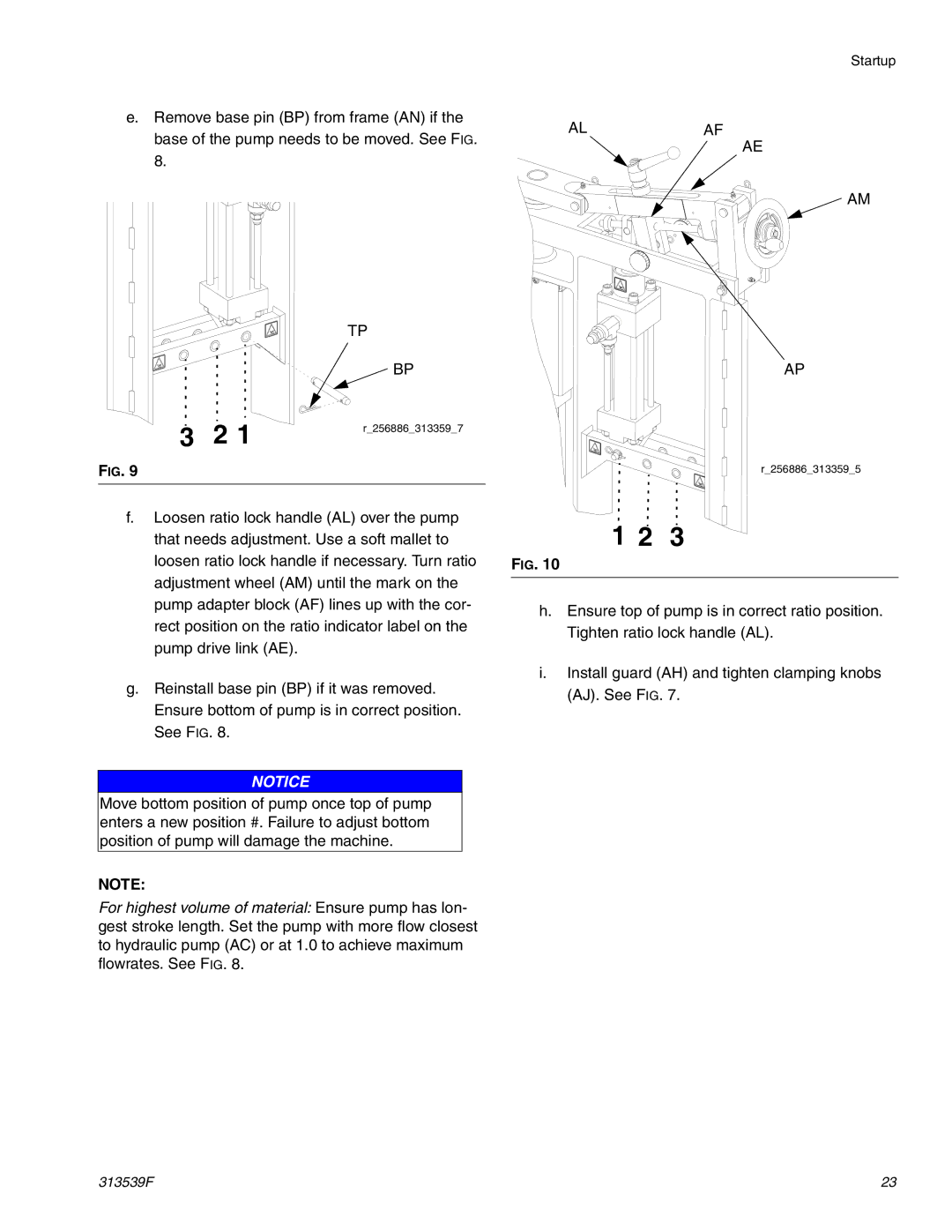
f.Loosen ratio lock handle (AL) over the pump that needs adjustment. Use a soft mallet to loosen ratio lock handle if necessary. Turn ratio adjustment wheel (AM) until the mark on the pump adapter block (AF) lines up with the cor- rect position on the ratio indicator label on the pump drive link (AE).
g.Reinstall base pin (BP) if it was removed. Ensure bottom of pump is in correct position. See FIG. 8.
NOTICE
Move bottom position of pump once top of pump enters a new position #. Failure to adjust bottom position of pump will damage the machine.
NOTE:
For highest volume of material: Ensure pump has lon- gest stroke length. Set the pump with more flow closest to hydraulic pump (AC) or at 1.0 to achieve maximum flowrates. See FIG. 8.
Startup
ALAF
AE
![]() AM
AM
AP
r_256886_313359_5
1 2 3
FIG. 10
h.Ensure top of pump is in correct ratio position. Tighten ratio lock handle (AL).
i.Install guard (AH) and tighten clamping knobs (AJ). See FIG. 7.
313539F | 23 |