SECTION 4: IDENTIFICATION
1
2
3
5
4
6
7 ![]()
8
16
15
![]() 13
13
12
11
10
9
14
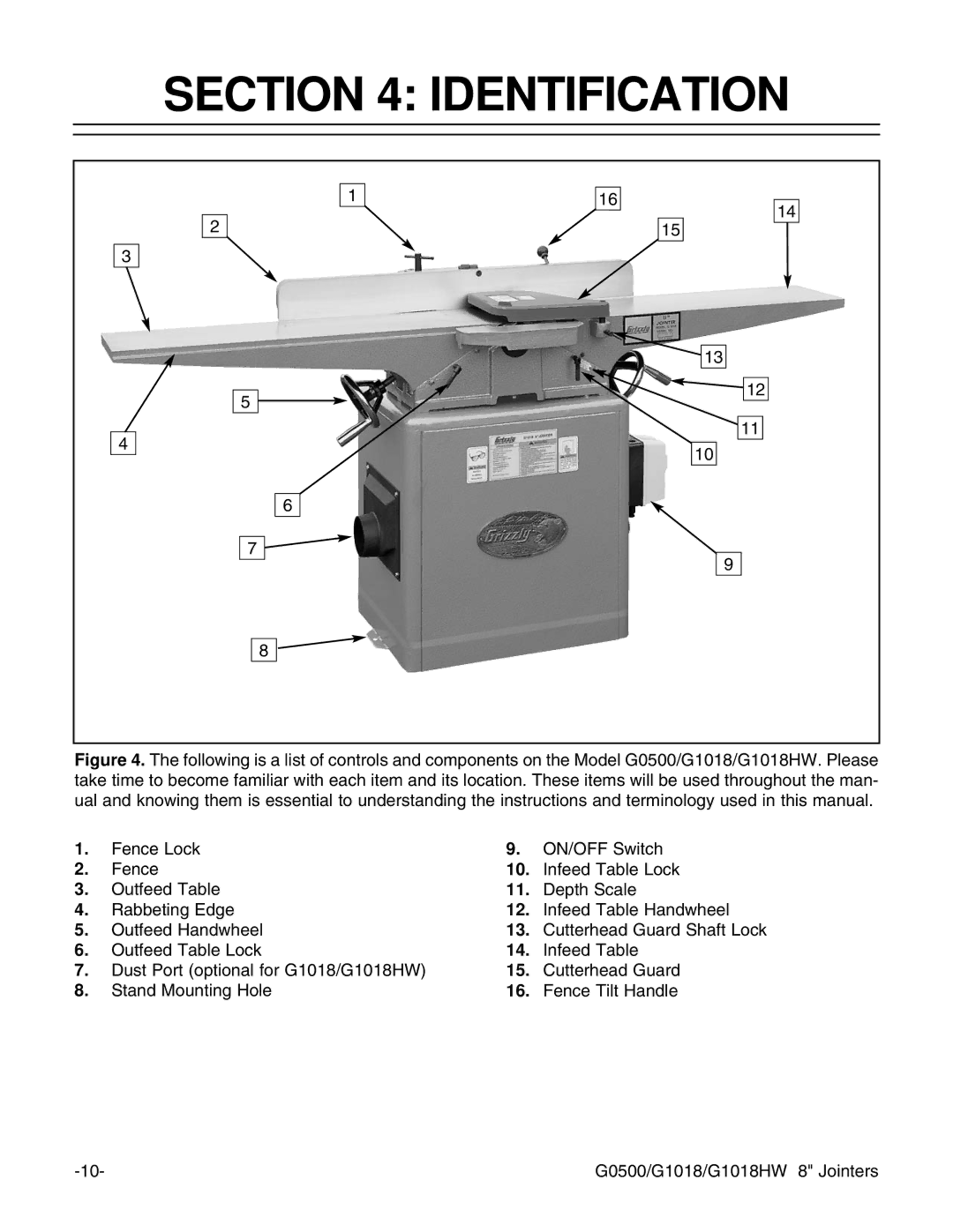
Figure 4. The following is a list of controls and components on the Model G0500/G1018/G1018HW. Please take time to become familiar with each item and its location. These items will be used throughout the man- ual and knowing them is essential to understanding the instructions and terminology used in this manual.
1. | Fence Lock | 9. | ON/OFF Switch |
2. | Fence | 10. | Infeed Table Lock |
3. | Outfeed Table | 11. | Depth Scale |
4. | Rabbeting Edge | 12. | Infeed Table Handwheel |
5. | Outfeed Handwheel | 13. | Cutterhead Guard Shaft Lock |
6. | Outfeed Table Lock | 14. | Infeed Table |
7. | Dust Port (optional for G1018/G1018HW) | 15. | Cutterhead Guard |
8. | Stand Mounting Hole | 16. | Fence Tilt Handle |
G0500/G1018/G1018HW 8" Jointers |
