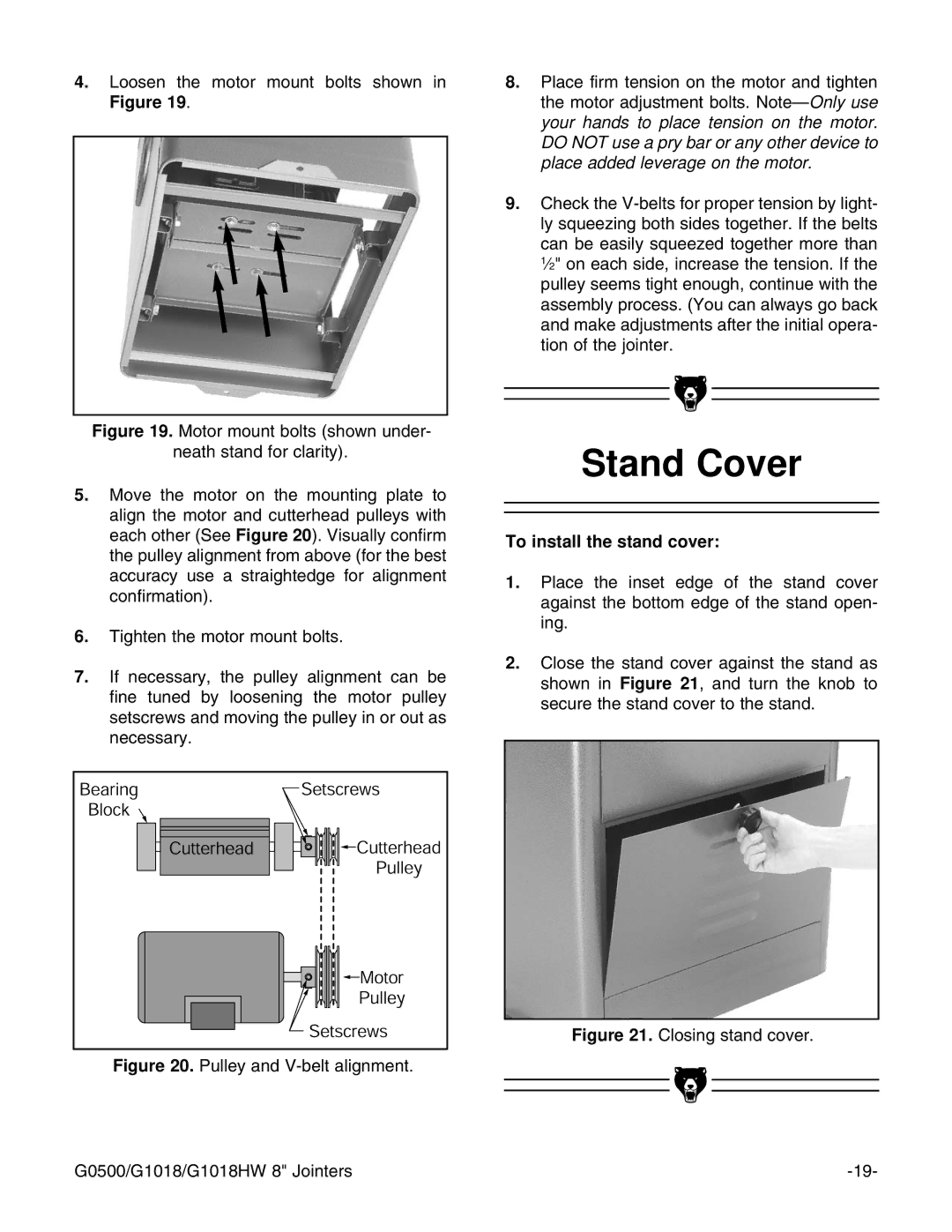
4.Loosen the motor mount bolts shown in Figure 19.
Figure 19. Motor mount bolts (shown under-
neath stand for clarity).
5.Move the motor on the mounting plate to align the motor and cutterhead pulleys with each other (See Figure 20). Visually confirm the pulley alignment from above (for the best accuracy use a straightedge for alignment confirmation).
6.Tighten the motor mount bolts.
7.If necessary, the pulley alignment can be fine tuned by loosening the motor pulley setscrews and moving the pulley in or out as necessary.
Figure 20. Pulley and V-belt alignment.
8.Place firm tension on the motor and tighten the motor adjustment bolts. Note—Only use your hands to place tension on the motor. DO NOT use a pry bar or any other device to place added leverage on the motor.
9.Check the V-belts for proper tension by light- ly squeezing both sides together. If the belts can be easily squeezed together more than 1⁄2" on each side, increase the tension. If the pulley seems tight enough, continue with the assembly process. (You can always go back and make adjustments after the initial opera- tion of the jointer.
Stand Cover
To install the stand cover:
1.Place the inset edge of the stand cover against the bottom edge of the stand open- ing.
2.Close the stand cover against the stand as shown in Figure 21, and turn the knob to secure the stand cover to the stand.
Figure 21. Closing stand cover.
G0500/G1018/G1018HW 8" Jointers |
