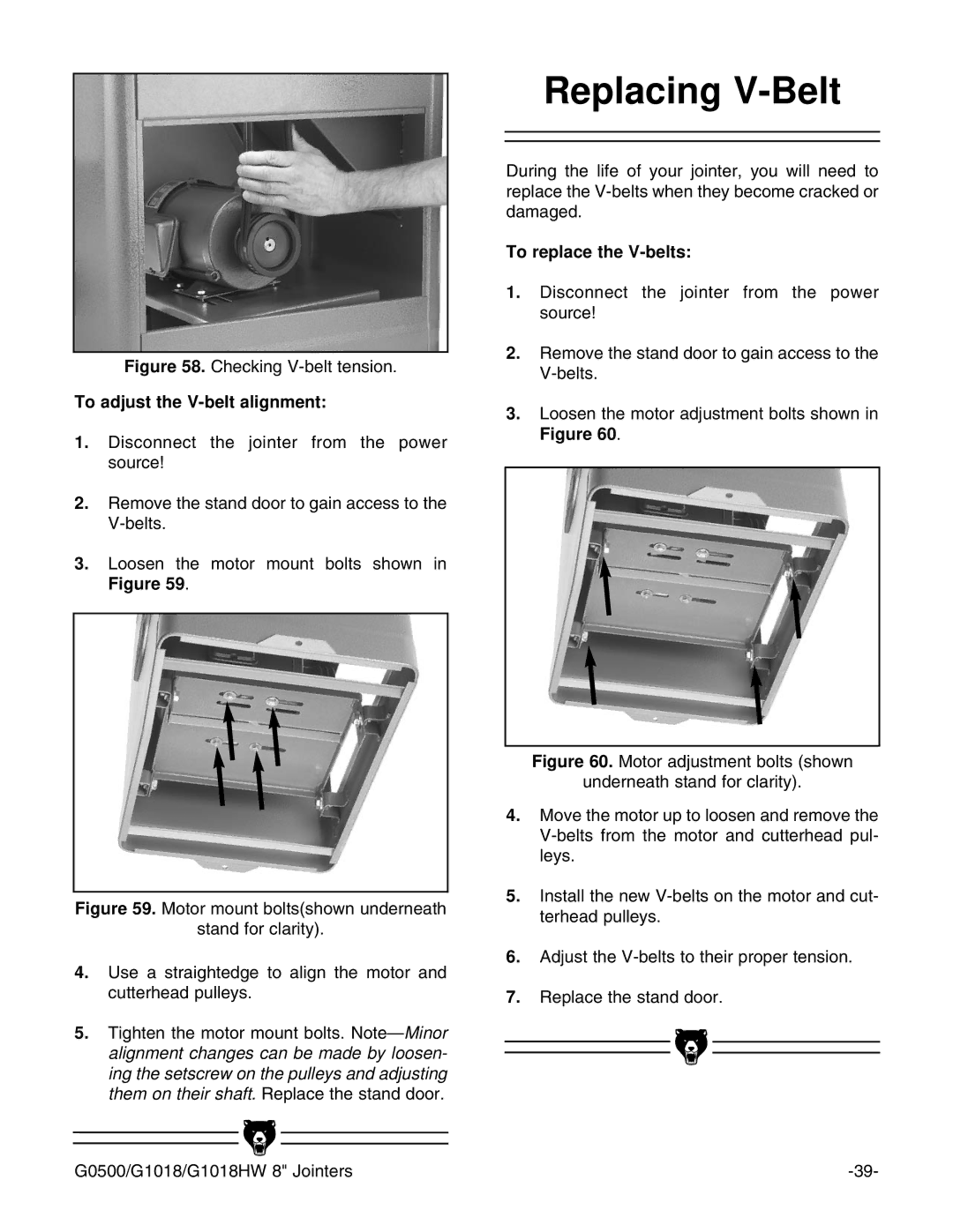
Figure 58. Checking V-belt tension.
To adjust the V-belt alignment:
1.Disconnect the jointer from the power source!
2.Remove the stand door to gain access to the
3.Loosen the motor mount bolts shown in Figure 59.
Figure 59. Motor mount bolts(shown underneath
stand for clarity).
4.Use a straightedge to align the motor and cutterhead pulleys.
5.Tighten the motor mount bolts. Note—Minor alignment changes can be made by loosen- ing the setscrew on the pulleys and adjusting them on their shaft. Replace the stand door.
Replacing V-Belt
During the life of your jointer, you will need to replace the
To replace the V-belts:
1.Disconnect the jointer from the power source!
2.Remove the stand door to gain access to the
3.Loosen the motor adjustment bolts shown in Figure 60.
Figure 60. Motor adjustment bolts (shown
underneath stand for clarity).
4.Move the motor up to loosen and remove the V-belts from the motor and cutterhead pul- leys.
5.Install the new V-belts on the motor and cut- terhead pulleys.
6.Adjust the V-belts to their proper tension.
7.Replace the stand door.
|
|
|
|
|
|
|
|
|
|
|
|
G0500/G1018/G1018HW 8" Jointers | |||
