Powering the System
•The transformer is intended for indoor use. If the transformer can only be plugged into an outside electrical outlet, a weatherproof housing or cover (available at electrical supply stores) must be used.
•Solar power options are available; see Solar Chart on next page.
•All low voltage wire used for powering the GTO/PRO gate operators MUST be 16 gauge (minimum) dual conductor,
Step 21:
Choose the electrical outlet into which the transformer will be plugged. Measure the distance from the electrical outlet to the control box, following the path where the low voltage wire will laid (the maximum distance can be no more than 1000 ft.).
Gate Weight
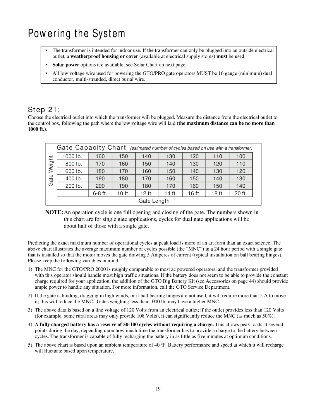
Gate Capacity Chart (estimated number of cycles based on use with a transformer)
1000 lb. | 160 | 150 | 140 | 130 | 120 | 110 | 100 |
800 lb. | 170 | 160 | 150 | 140 | 130 | 120 | 110 |
600 lb. | 180 | 170 | 160 | 150 | 140 | 130 | 120 |
400 lb. | 190 | 180 | 170 | 160 | 150 | 140 | 130 |
200 lb. | 200 | 190 | 180 | 170 | 160 | 150 | 140 |
| 10 ft. | 12 ft. | 14 ft. | 16 ft. | 18 ft. | 20 ft. |
Gate Length
NOTE: An operation cycle is one full opening and closing of the gate. The numbers shown in this chart are for single gate applications, cycles for dual gate applications will be about half of those with a single gate.
Predicting the exact maximum number of operational cycles at peak load is more of an art form than an exact science. The above chart illustrates the average maximum number of cycles possible (the “MNC”) in a 24 hour period with a single gate that is installed so that the motor moves the gate drawing 5 Amperes of current (typical installation on ball bearing hinges). Please keep the following variables in mind:
1)The MNC for the GTO/PRO 2000 is roughly comparable to most ac powered operators, and the transformer provided with this operator should handle most high traffic situations. If the battery does not seem to be able to provide the constant charge required for your application, the addition of the GTO Big Battery Kit (see Accessories on page 44) should provide ample power to handle any situation. For more information, call the GTO Service Department.
2)If the gate is binding, dragging in high winds, or if ball bearing hinges are not used, it will require more than 5 A to move it; this will reduce the MNC. Gates weighing less than 1000 lb. may have a higher MNC.
3)The above data is based on a line voltage of 120 Volts from an electrical outlet; if the outlet provides less than 120 Volts (for example, some rural areas may only provide 108 Volts), it can significantly reduce the MNC (as much as 50%).
4)A fully charged battery has a reserve of
5)The above chart is based upon an ambient temperature of 40 ºF. Battery performance and speed at which it will recharge will fluctuate based upon temperature.
19