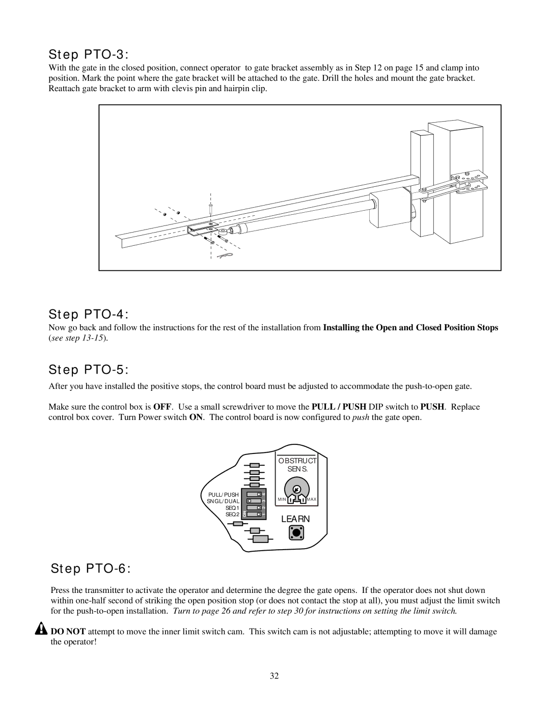
Step PTO-3:
With the gate in the closed position, connect operator to gate bracket assembly as in Step 12 on page 15 and clamp into position. Mark the point where the gate bracket will be attached to the gate. Drill the holes and mount the gate bracket. Reattach gate bracket to arm with clevis pin and hairpin clip.
Step PTO-4:
Now go back and follow the instructions for the rest of the installation from Installing the Open and Closed Position Stops (see step
Step PTO-5:
After you have installed the positive stops, the control board must be adjusted to accommodate the
Make sure the control box is OFF. Use a small screwdriver to move the PULL / PUSH DIP switch to PUSH. Replace control box cover. Turn Power switch ON. The control board is now configured to push the gate open.
PULL/PUSH
SNGL/DUAL
SEQ1
SEQ2
|
|
|
|
|
|
|
|
|
|
|
| 4 |
| |
|
|
| ||
|
| 3 |
| |
|
| 2 |
| |
ON |
| 1 |
| |
|
|
|
|
|
|
|
|
|
|
|
|
|
|
|
|
|
|
|
|
|
|
|
|
|
|
|
|
|
|
OBSTRUCT | |
| SENS. |
MIN | MAX |
LEARN | |
Step PTO-6:
Press the transmitter to activate the operator and determine the degree the gate opens. If the operator does not shut down within
![]() DO NOT attempt to move the inner limit switch cam. This switch cam is not adjustable; attempting to move it will damage the operator!
DO NOT attempt to move the inner limit switch cam. This switch cam is not adjustable; attempting to move it will damage the operator!
32