Installing The Second Unit
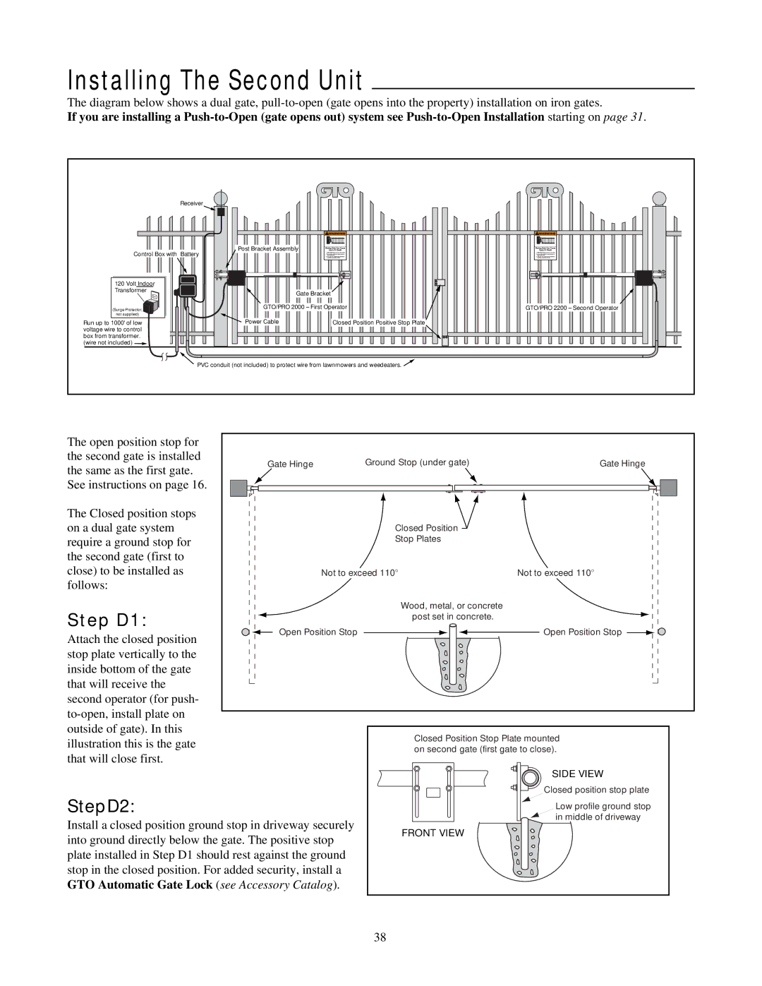
The diagram below shows a dual gate,
If you are installing a
Receiver
Control Box with Battery
120 Volt Indoor
Transformer
(Surge Protector,
not supplied)
Run up to 1000' of low voltage wire to control box from transformer. (wire not included) ![]()
Post Bracket Assembly |
|
|
Gate Bracket |
|
|
GTO/PRO 2000 – First Operator | GTO/PRO 2200 – Second Operator | |
Power Cable | Closed Position Positive Stop Plate |
|
PVC conduit (not included) to protect wire from lawnmowers and weedeaters. ![]()
The open position stop for |
|
|
| |
the second gate is installed | Gate Hinge | Ground Stop (under gate) | Gate Hinge | |
the same as the first gate. | ||||
|
|
| ||
See instructions on page 16. |
|
|
| |
The Closed position stops |
|
|
| |
on a dual gate system |
| Closed Position |
| |
require a ground stop for |
| Stop Plates |
| |
the second gate (first to |
|
|
| |
close) to be installed as |
| Not to exceed 110° | Not to exceed 110° | |
follows: |
|
|
| |
Step D1: |
| Wood, metal, or concrete |
| |
| post set in concrete. |
| ||
Open Position Stop | Open Position Stop | |||
Attach the closed position | ||||
|
|
| ||
stop plate vertically to the |
|
|
| |
inside bottom of the gate |
|
|
| |
that will receive the |
|
|
| |
second operator (for push- |
|
|
| |
|
|
| ||
outside of gate). In this |
| Closed Position Stop Plate mounted | ||
illustration this is the gate |
| |||
| on second gate (first gate to close). | |||
that will close first. |
| |||
|
|
| ||
|
|
| SIDE VIEW | |
| Closed position stop plate | |
StepD2: | Low profile ground stop | |
Install a closed position ground stop in driveway securely | in middle of driveway | |
FRONT VIEW | ||
into ground directly below the gate. The positive stop | ||
| ||
plate installed in Step D1 should rest against the ground |
| |
stop in the closed position. For added security, install a |
| |
GTO Automatic Gate Lock (see Accessory Catalog). |
|
38