StepD3:
Return to page 11, Single Gate Operator Installation, and repeat Step 1 through 15 to install the second operator. This time in Step 15, however, the closed position stop plate on the first gate will contact the leading edge of the second gate.
Connecting the Second Operator to the Control Board
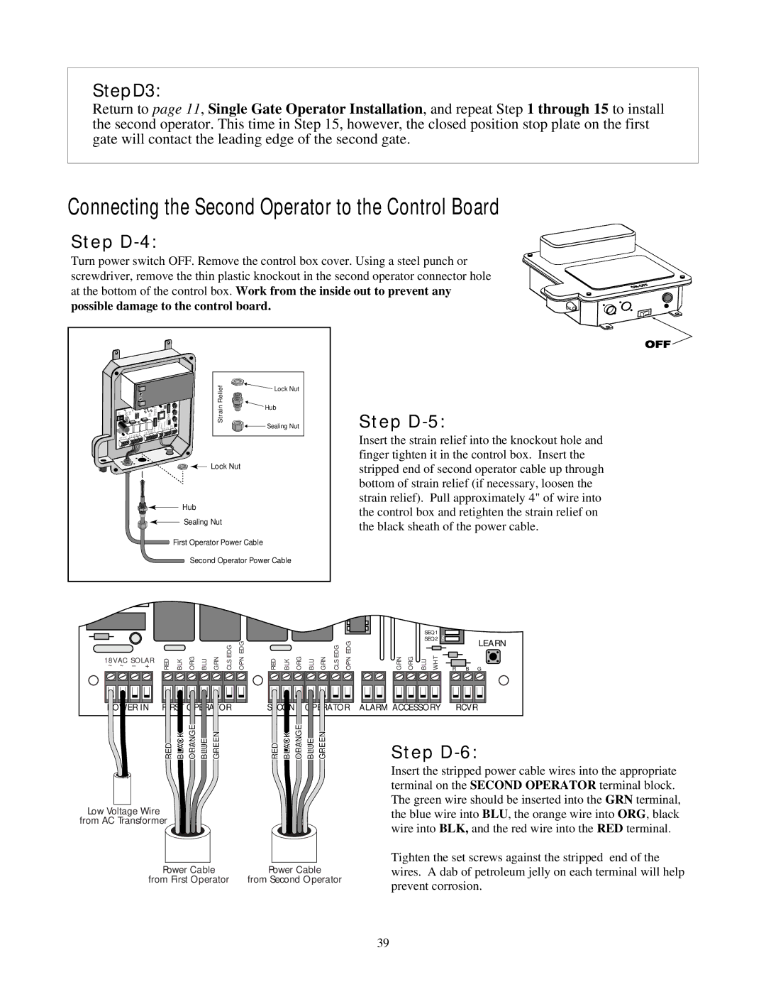
Step D-4:
Turn power switch OFF. Remove the control box cover. Using a steel punch or screwdriver, remove the thin plastic knockout in the second operator connector hole at the bottom of the control box. Work from the inside out to prevent any
possible damage to the control board.
|
|
|
|
|
|
|
|
| CLOSE |
|
|
| Relief |
|
| Lock Nut |
|
|
|
| |||
|
|
|
|
|
|
|
|
|
|
|
|
|
|
|
|
|
|
|
|
| |||
|
|
|
|
|
| STATUS |
|
|
|
|
|
|
| Strain |
|
| Hub |
|
|
|
|
|
|
| + |
|
|
|
|
|
|
|
| LEARN |
|
|
|
|
|
|
|
|
|
| |||
|
|
|
|
|
|
|
| INERTI | A |
|
|
|
|
|
|
|
|
|
|
| |||
|
|
|
|
|
|
|
|
| OBSTR. |
|
|
|
|
|
|
|
|
|
|
|
| ||
|
|
|
|
|
|
|
|
| SENS. |
|
|
|
|
|
|
|
|
|
|
|
|
| |
1~8VAC~ SO– LA+R | RED BLK ORG BLU | GRN EDGCLS | EDGOPN | RED BLK ORG BLU GRN | ATORCLSEDG OPNEDG | ALARM | GRN ORG BLU WHT | R G | B |
|
|
|
|
|
| Sealing Nut |
|
|
|
| |||
ACCE |
|
|
|
|
|
|
|
|
|
|
|
|
|
|
| ||||||||
|
|
|
|
|
|
|
| SSORY | RCVR |
|
|
|
|
|
|
|
|
|
|
|
|
| |
|
|
|
| SECOND OPER |
|
|
|
|
|
|
|
|
|
|
|
|
|
|
|
|
|
|
|
| FIRST OPER | ATOR |
|
|
|
|
|
|
|
|
|
|
|
|
|
|
|
|
|
|
|
|
|
POWER IN |
|
|
|
|
|
|
|
|
|
|
|
|
|
|
|
|
|
|
|
|
|
| |
|
|
|
|
|
|
|
|
|
|
|
|
|
|
|
|
|
|
|
|
|
|
| |
|
|
|
|
|
|
|
|
|
|
|
|
|
| Lock Nut |
|
|
|
|
|
|
| ||
|
|
|
|
|
|
|
|
|
|
|
| Hub |
|
|
|
|
|
|
|
|
|
|
|
|
|
|
|
|
|
|
|
|
|
|
| Sealing Nut |
|
|
|
|
|
|
|
|
| ||
|
|
|
|
|
|
|
|
|
| First Operator Power Cable |
|
|
|
|
|
|
| ||||||
|
|
|
|
|
|
|
|
|
|
|
| Second Operator Power Cable |
|
|
|
|
| ||||||
~ ~ | – |
|
| + |
|
| RED |
|
| BLK | ORG | BLU | GRN | CLSEDG | OPNEDG | RED | BLK | ORG | BLU | GRN | CLSEDG | OPNEDG | |
18VAC SOLAR |
|
|
|
|
|
|
|
|
|
|
|
|
|
|
|
|
|
| |||||
POWER IN FIRST OPERATOR | SECOND OPERATOR |
Step D-5:
Insert the strain relief into the knockout hole and finger tighten it in the control box. Insert the stripped end of second operator cable up through bottom of strain relief (if necessary, loosen the strain relief). Pull approximately 4" of wire into the control box and retighten the strain relief on the black sheath of the power cable.
SEQ1 | ON |
|
| ||
SEQ2 |
| LEARN | |||
|
|
|
|
| |
GRN ORG | BLU | WHT | R | B G |
|
|
| ||
ALARM ACCESSORY |
| RCVR | ||
RED | BLACK | ORANGE | BLUE | GREEN | RED | BLACK | ORANGE | BLUE | GREEN |
Low Voltage Wire
from AC Transformer
Power Cable | Power Cable |
from First Operator | from Second Operator |
Step D-6:
Insert the stripped power cable wires into the appropriate terminal on the SECOND OPERATOR terminal block. The green wire should be inserted into the GRN terminal, the blue wire into BLU, the orange wire into ORG, black wire into BLK, and the red wire into the RED terminal.
Tighten the set screws against the stripped end of the wires. A dab of petroleum jelly on each terminal will help prevent corrosion.
39