Repeat the procedure as needed until all chan- nels requiring adjustment have been set. When all adjustments have been made and no further adjustments are made for five seconds, the AVR will return to normal operation.
If you are using a disc with noise test signals or an external signal generator as the source from which to trim the output levels, you may use the EzSet feature of the remote to guide you to the correct SPL level. To use the remote for this pur- pose, start the test tone from the source and press and quickly release the SPL Indicator
Select to activate the sensor.
While the test tone is played, the Program/SPL Indicator 2will change color to indicate the level. When it is red, the level is too high; when it is orange, the level is too low. To set the refer-
ence level, open the Volume Control until the SPL Indicator´s LED lights green when the test signal is fed to the left front speaker. Then adjust the level of all other speakers, while they are receiving the test signal, until the LED lights green for all channels. After the output levels for all channels are aligned, press the SPL
Indicator Select | to turn the sensor and |
indicator off. | |
The channel output may also be adjusted using the full-OSD on-screen menu system. First, set the volume to a comfortable listening level using the Volume Control ı . Then, press the OSD button Lto bring up the
MASTER MENU (Figure 1). Press the ¤ Button Dfour times until the on-screen › cursor is next to the CHANNEL ADJUST line. Press the Set Button Fto activate the CHANNEL ADJUST menu (Figure 10).
| * C H A N N E L A D J U S T * |
→ | F L | : 0 d B | S B R : 0 | d B |
|
| C E N : 0 d B | S B L : 0 | d B |
| F R | : 0 d B | S L | : 0 | d B |
| S R | : 0 d B | S U B : 0 | d B |
| C H A N N E L R E S E T | : O F F |
| T E S T T O N E S E Q | : M A N U A L |
| T E S T T O N E | | : O F F |
B A C K T O A U D I O S E T U P
Figure 10
When the menu appears, the internal test tone will be turned off. This will allow you to use your external test disc or other source material as the test signal. Then, use the ⁄/¤ Buttons Dto select the channels to be adjusted. At each channel position use the ‹/ › Buttons E
to change the output level.
Remember, when you are using a disc with test signal (e.g. pink noise) or an external signal generator as the source, the goal is to have the output level at each channel be equal when heard at the listening position, with any surround mode selected. When your test source is a nor- mal disc with music signals, you may adjust the
level for each channel and surround mode as you prefer, e.g. you may lower the center channel level when you find it to be too high or increase the level of the rears when you find it to be too low with specific surround modes.
If you wish to reset all the levels to their original factory default of 0dB offset, press the ⁄/¤ Buttons Dso that the on-screen cursor is next to the CHANNEL RESET line and press the ‹/ › Buttons E so that the word ON is highlighted. After the levels are reset, resume the procedure outlined above to reset the levels to the desired settings. When all adjustments are done, press the ⁄/¤ Buttons
Dto move the on-screen➞ cursor so that it is next to BACK TO MASTER MENU and then press the Set Button Fif you wish to go back to the main menu to make other adjust- ments. If you have no other adjustments to make, press the OSD Button Lto exit the menu system.
NOTE: The output levels may be separately trimmed for each digital and analog surround mode. If you wish to have different trim levels for a specific mode, select that mode and then follow the instructions in the steps shown above.
With Stereo and Vmax modes the adjustment procedure described above is the only way to trim the output level, e.g. to match the Stereo or Vmax level with other modes.
Memory Backup
This product is equipped with a memory backup system that preserves tuner presets and system configuration information if the unit is turned off completely, accidentally unplugged or subjected to a power outage. This memory will last for approximately two weeks, after which time all information must be reentered.
The AVR 235 is equipped with a number of ad- vanced features that add extra flexibility to the unit’s operation. While it is not necessary to use these features to operate the unit, they provide additional options that you may wish to use.
Front-Panel-Display Fade
In normal operation, the front-panel displays and indicators remain on at full brightness, although you may also dim them or turn them off as shown on page 34. As an additional option, you may also set the AVR so that the displays are on whenever a button is pressed on the front panel or remote, but then fade out after a set period of time.
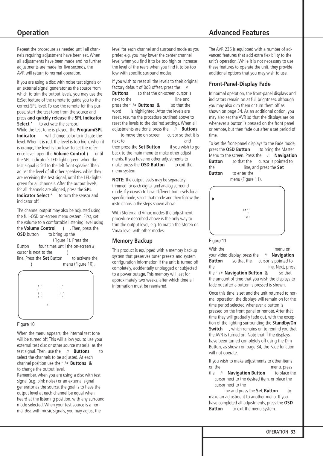
To set the front-panel displays to the Fade mode, press the OSD Button Lto bring the Master Menu to the screen. Press the ⁄/¤ Navigation Button Dso that the ➞ cursor is pointed to the ADVANCED line, and press the Set Button Fto enter the ADVANCED SELECT menu (Figure 11).
* | A D V A N C E D | S E L E C T | * |
V F D F A D E T I M E O U T : O F F |
V F D | : F U L L | | |
V O L U M E D E F A U L T : O F F | |
D E F A U L T V O L | S E T : | |
| | |
S E M I O S D T I M E | O U T : 5 S |
F U L L O S D T I M E | O U T : 2 0 S |
D E F A U L T | S U R R M O D E : O N |
B A C K T O | M A S T E R M E N U |
Figure 11
With the ADVANCED SELECT menu on your video display, press the ⁄/¤ Navigation Button Dso that the ➞ cursor is pointed to the VFD FADE TIME OUT line. Next, press the ‹/ › Navigation Button E so that the amount of time that you wish the displays to fade out after a button is pressed is shown.
Once this time is set and the unit returned to nor- mal operation, the displays will remain on for the time period selected whenever a button is pressed on the front panel or remote. After that time they will gradually fade out, with the excep- tion of the lighting surrounding the Standby/On Switch 3, which remains on to remind you that the AVR is turned on. Note that if the displays have been turned completely off using the Dim Button, as shown on page 34, the Fade function will not operate.
If you wish to make adjustments to other items on the ADVANCED SELECT menu, press the ⁄/¤ Navigation Button Dto place the
➞cursor next to the desired item, or place the
➞cursor next to the BACK TO MASTER MENU line and press the Set Button Fto make an adjustment to another menu. If you have completed all adjustments, press the OSD Button Lto exit the menu system.