WARNING: DO NOT CONNECT 230 VAC ! TOTHEWALLSWITCHORTHECONTROL
VALVE WILL BE DESTROYED.
CAUTION | LABEL ALL WIRES PRIOR TO DISCONNECTION | ||
| WHEN SERVICING CONTROLS. WIRING ERRORS | ||
| CAN CAUSE IMPROPER AND DANGEROUS OP- | ||
| ERATION. VERIFY PROPER OPERATION AFTER | ||
| SERVICING. |
| |
|
|
|
|
OPTIONAL WALL SWITCH |
|
|
|
THERMOSTAT OR REMOTE |
|
|
|
|
|
| THERMOCOUPLE |
|
|
| TP/TH |
| OFF |
| TP |
|
| TH | |
|
|
| |
| ON | THERMOPILE |
|
| ON/OFF |
| |
REMOTE SWITCH |
| GAS VALVE | |
SWITCH |
| ||
PIGTAIL |
|
| |
|
|
| |
|
|
|
|
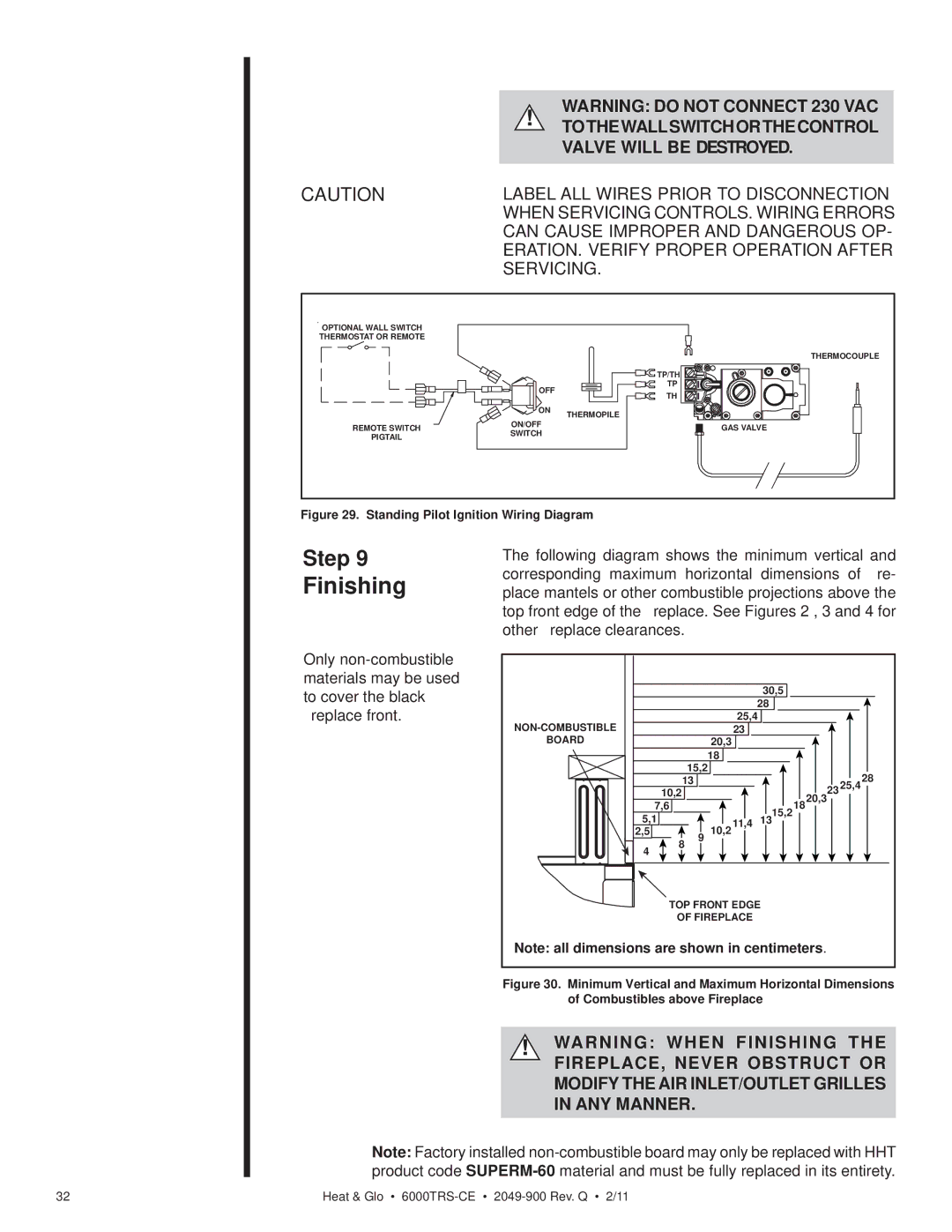
Figure 29. Standing Pilot Ignition Wiring Diagram
Step 9
Finishing
Only
The following diagram shows the minimum vertical and corresponding maximum horizontal dimensions of fire- place mantels or other combustible projections above the top front edge of the fireplace. See Figures 2 , 3 and 4 for other fireplace clearances.
|
|
|
|
| 30,5 |
|
|
|
|
|
|
|
| 28 |
|
|
|
|
|
| 25,4 |
|
|
| ||
|
|
| 23 |
|
|
|
| |
BOARD |
|
| 20,3 |
|
|
|
|
|
|
|
| 18 |
|
|
|
|
|
| 15,2 |
|
|
|
| 28 | ||
| 13 |
|
|
|
|
| 2325,4 | |
| 10,2 |
|
|
|
| 1820,3 |
| |
| 7,6 |
|
|
| 15,2 |
|
| |
5,1 |
|
| 11,4 |
|
|
| ||
9 | 10,2 | 13 |
|
|
| |||
2,5 | 8 |
|
|
|
|
| ||
4 |
|
|
|
|
|
|
| |
|
|
|
|
|
|
|
| |
TOP FRONT EDGE
OF FIREPLACE
Note: all dimensions are shown in centimeters.
Figure 30. Minimum Vertical and Maximum Horizontal Dimensions of Combustibles above Fireplace
!WARNING: WHEN FINISHING THE FIREPLACE, NEVER OBSTRUCT OR MODIFY THE AIR INLET/OUTLET GRILLES IN ANY MANNER.
Note: Factory installed
32 | Heat & Glo • |