•What to do if you smell gas
NOTICE
Owner’s Manual
Homeowner Reference Information
A. Congratulations
3 Maintenance and Service
Table of Contents
Safety Alert Key
Installer Guide
13 Finishing
14 Appliance Setup
15 Troubleshooting
= Contains updated information
WARRANTY COVERAGE
B. Limited Lifetime Warranty
LIMITED LIFETIME WARRANTY
Hearth & Home Technologies Inc
This warranty is void if
B. Limited Lifetime Warranty continued
WARRANTY CONDITIONS
WARRANTY EXCLUSIONS
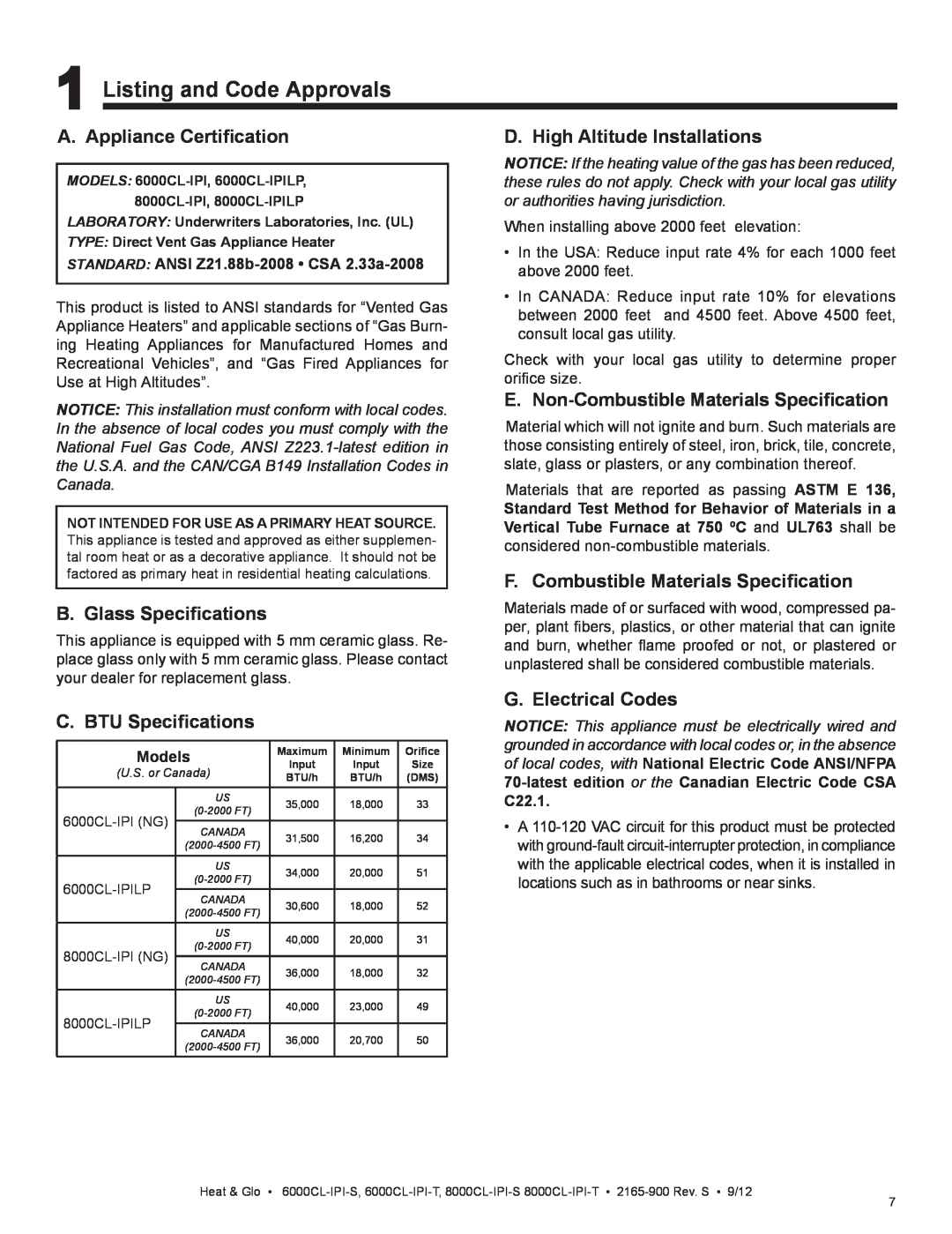
E. Non-CombustibleMaterials Specification
B. Glass Specifications
C. BTU Specifications
D. High Altitude Installations
Inspection
Installation of Carbon Monoxide Detectors
Approved Carbon Monoxide Detectors
Signage
2 Operating Instructions User Guide
A. Gas Fireplace Safety
B. Your Fireplace
E. Decorative Doors and Fronts
F. Fixed Glass Assembly
C. Fan Kit optional
D. Clear Space
5.Module Reset
H. IPI Battery Tray/Battery Installation
I. Control Module Operation
J. Before Lighting Fireplace
K. Lighting Instructions IPI
FOR YOUR SAFETY READ BEFORE LIGHTING
LIGHTING INSTRUCTIONS IPI
TO TURN OFF GAS TO APPLIANCE
•Smoke detectors may activate
M. Frequently Asked Questions
L. After Fireplace is Lit
•Some people may be sensitive to smoke and odors
Remote Control
3 Maintenance and Service
A. Maintenance Tasks-Homeowner
Glass Cleaning
Firebox
B.Maintenance Tasks-QualifiedService Technician
Gasket Seal and Glass Assembly Inspection
Logs
Note: Refractory is Fragile
C.Refractory, Grate and Valve Assembly Removal
BASE REFRACTORY
D. Burner Identification/Verification
OPTIONAL WALL SWITCH SECTION 12.C
4 Getting Started
A. Typical Appliance System
Installer Guide
C. Tools and Supplies Needed
B. Design and Installation Considerations
D. Inspect Appliance and Components
5 Framing and Clearances
C. Clearances
B. Constructing the Appliance Chase
If A minimum is ____, then B maximum is_____
D. Mantel and Wall Projections
Combustible Mantels
Combustible Mantel Legs or Wall Projections
H Min. Ft
6 Termination Locations
A. Vent Termination Minimum Clearances
Roof Pitch
Covered Alcove Applications
= AREA WHERE TERMINAL IS NOT PERMITTED
V= VENT TERMINAL X = AIR SUPPLY INLET
C. Use of Elbows
7 Vent Information and Diagrams
A. Approved Pipe
B. Vent Table Key
Top Vent - Horizontal Termination
E. Vent Diagrams
Top Vent - Horizontal Termination
One Elbow
INSTALLED HORIZONTALLY
Two Elbows
V1 Min
Top Vent - Horizontal Termination - continued
Three Elbows
H2 V2
BREAK
Top Vent - Vertical Termination No Elbow
V1 = 40 ft. Max. 12.4 m V1 = 3 ft. Min. 914 mm
Flue Restrictor Instructions
Two Elbows
Top Vent - Vertical Termination continued
Three Elbows
Top Vent - Vertical Termination - continued
Figure
Rear Vent - Horizontal Termination No Elbow
H1 = 16 in. 406 mm Maximum
One 45º Elbow
Rear Vent - Horizontal Termination - continued
V1 H1
Two Elbows
H1 Maximum
V1 H1
Three Elbows
6000CL
Two Elbows
Rear Vent - Vertical Termination One Elbow
V1 H1
H1 H2
Rear Vent - Vertical Termination - continued
Three Elbows
Three Elbows
•Between ceiling firestops
8 Vent Clearances and Framing
A. Pipe Clearances to Combustibles
B. Wall Penetration Framing
C. Install the Ceiling Firestop
Vaulted Ceiling Installation
D. Install Attic Insulation Shield
E. Installing the Optional Heat-Zone Gas Kit
Flat Ceiling Installation
A. Top Vent
9 Appliance Preparation
B. Rear Vent
•Sagging or loose insulation
C. Installing the Non-combustibleBoard
D. Securing and Leveling the Appliance
WARNING! Risk of Fire! Prevent contact with
Lances
10 Installing Vent Pipe DVP and SLP Pipe
A. Assemble Vent Sections DVP Pipe Only
Attach Vent to the Firebox Assembly
continuous exposure rating sealant
B. Assemble Vent Sections SLP Pipe Only
C. Assemble Slip Sections
Pilot hole
E. Disassemble Vent Sections
D. Secure the Vent Sections
F. Install Decorative Ceiling Components SLP only
H. Assemble and Install Storm Collar
G. Install Metal Roof Flashing
CAULK
J.Install Decorative Wall Components SLP only
I. Install Vertical Termination Cap
shown in Figure
depth without using additional pipe sections
Cap Specification Chart
C. Gas Connection
11 Gas Information
A. Fuel Conversion
B. Gas Pressure
12 Electrical Information
A. Wiring Requirements
B. IntelliFire PlusTM Ignition System Wiring
C. Optional Accessories Requirements
NOTICE: DO NOT wire
D. Electrical Service and Repair
E. Junction Box Installation
F. Wall Switch Installation for Fan Optional
Combustible Mantels
13 Finishing
A. Mantel and Wall Projections
B. Facing Material
Finishing Material 1 Inch Thick or Less
C. Doors
Remove Finishing Strips. See Figure
Finishing Material Thickness
Finishing Material Thickness
1-4inches maximum
0-4inches maximum
Figure 13.7 Removing Finishing Strips
Removal of Finishing Strips
Figure 13.8. Clean Face Door Dimensions
FINISHING STRIPS REMOVED
MARBLE LEG CUT
D. Elevated Hearth Systems
DIMENSION
ELEVATED APPLIANCE
D. Accessories
14 Appliance Setup
A. Remove Fixed Glass Assembly
C. Clean the Appliance
CAUTION! Risk of Cuts, Abrasions or Flying Debris
F. Refractory Installation
Step 1. Back Refractory Panel Installation
Step 2. Right Refractory Panel Installation
REFRACTORY PANEL MUST BEFLUSH WITHNO GAPS
Step 3. Left Refractory Installation
G. Ember Placement
Step 4. Top Refractory Installation
6000CL-IPI-T, 6000CL-IPILP-T
Log Assembly: LOGS-6CL
H. Install the Log Assembly
Models 6000CL-IPI-S, 6000CL-IPILP-S
RIGHT GRATE TINE
1 23
1 23 4
45 6
LOG PLACEMENTINDENTATIONS LOG PLACEMENT TABS
Log Assembly: LOGS-8CL
Models: 8000CL-IPI-S, 8000CL-IPILP-S
8000CL-IPI-T, 8000CL-IPILP-T
HORIZONTAL GRATE BAR
1 23
1 23 4
RIGHT GRATE TINE
Removing Fixed Glass Assembly
I. Fixed Glass Assembly
J. Install Trim and/or Surround
K. Air Shutter Setting
Possible Cause
15 Troubleshooting
A. IntelliFire PlusTM Ignition System
Symptom
Corrective Action
Troubleshooting continued
Symptom
Possible Cause
16 Reference Materials
A. Appliance Dimension Diagram
2-3/8
Heat & Glo •
B. Vent Components Diagrams
Height: 24 in./610 mm
DVP-AS2
DVP-TRAPK1
B. Vent Components Diagrams continued
DVP-TRAP1
DVP-TRAP2
31 in
B. Vent Components Diagrams continued
12 in
B. Vent Components Diagrams continued
PART NUMBER
B. Vent Components Diagrams continued
Optional Wire Harness
DESCRIPTION
6-1/2in
B. Vent Components Diagrams continued
8 in.203 mm Heat Shield 15-1/8in 384 mm
B. Vent Components Diagrams continued
14 in 356 mm 10-9/16in 269 mm SLP-CCS-BK
B. Vent Components Diagrams continued
Stocked
Log Set Assembly
C. Service Parts
6000CL-IPI-T, 6000CL-IPI-S
at Depot
Service Parts
8000CL-IPI-T, 8000CL-IPI-S
Log Set Assembly
#19 Control Assembly
6000CL-IPI, 8000CL-IPI
Service Parts
#18 Valve Assembly
Stocked
Service Parts
6000CL-IPI, 8000CL-IPI
at Depot
NOTES
D. Contact Information
NOTICE