DL.2 Digital Light With Collage Software
Contacting High End Systems
Patents
Iii
Declaration of Conformity
Product Modification Warning
Symbols
Returning an Item Under Warranty for Repair
Vii
Viii
Do I need any other permissions to use this material?
Table of Contentsii
DL.2 Menu System
DMX Programming Basics and Quick Start
Graphics Engine Overview
Xii
Xiii
Defining a Media File Segment
Xiv
Invert Black and White, Keep Color
Global Functions Collage Generator Effect
153
Xvi
Xvii
Fixture Motion Functions
Xviii
Content Management Application CMA
Xix
Maintenance and Troubleshooting
Restoring the System
Xxi
Xxii
Chapter Product Overview
Features
System
Content Management Application
Graphics Engine
Hardware
Related Products and Optional Accessories
Part Description
Hardware Setup
Chapter Setup and Configuration
Unpacking the Fixture
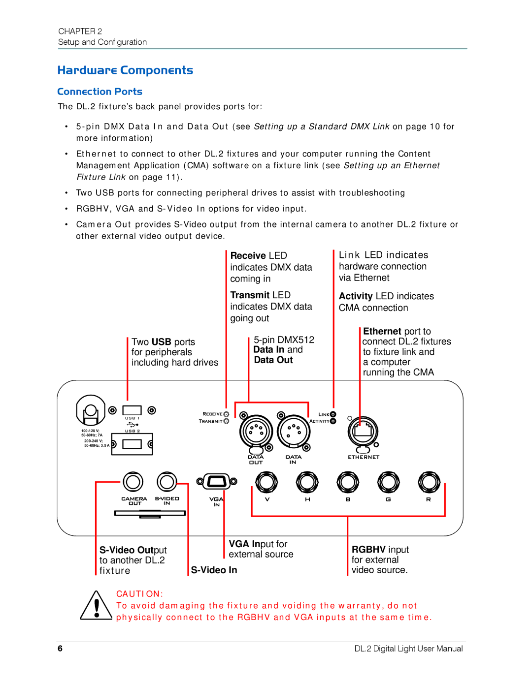
Hardware Components
Connection Ports
Attaching a Power Cord Cap
Installing a Line Cord Cap U.K. Only
Pan and Tilt Locking
Vatic Fitter Heads Information Danmark
Mounting the Fixture
Fog Machine Warning
Mounting the Fixture Upright
Truss Mounting
Setting up a Standard DMX Link
Linking DL.2 Fixtures
Setting up an Ethernet Fixture Link
Linking Configurations
Powering On the Fixture
Homing the Fixture
DL.2 Menu Display Panel
Software Setup
Verifying and Upgrading Fixture and CMA Software
Major.Minor.Build
Configuring DL.2 Fixtures
Setup Configuration Using the Menu System
Setup Configuration Using the CMA
Patching the DL.2 Fixture to a Wholehog Console
DMX Control Setup
Viewing Output
Recommended Shutdown Options
Shutting Down the Fixture
Placing Fixture in Road Case
Bring sides of case together and latch
Chapter DL.2 Menu System
Menu Panel Components
LCD Display Adjustment Buttons
LCD Display Power Button
Menu Menu Select LCD Power Display LED
LCD Display Menu Options and Selection
Navigating the Menu
Tab Select Buttons
DL.2 Menu Options
DMX
Main
Troubleshooting
DMX Tab
Menu Screen Descriptions
DMXControl Screen
DMXProtocol Tab
DMXProtocolMotion Screen
DMXProtocol Global Screen
DMXProtocol Obj Screens
DMXRaw Screen
Set Tab
SetFixture Screen
Restoring Factory Defaults
SetProjector Screen
Projector Menu Default Command
File Screen
TestHome Screen
Test Tab
TestSelf Test Screen
Info Tab
InfoHours
InfoVersion Screen
InfoStatus Tab
Reset Screen
Chapter
Chapter DMX Programming Basics and Quick Start
DMX Programming Overview
DMX512 Links
Bit vs -bit DMX Parameters
Determining a DMX Start Channel
Protocol DMX Channel Range Selection Axon DL.2
DL.2 Protocol Levels
Description Obj
Axon Protocol Levels
Chan Description Obj 1 Obj 2 Obj
Lighting Console Tips
Fixture Libraries
Patching DL.2 Fixtures and Axon Media Servers
DMX Output Displays
Wholehog III Programming Notes
Play Speed
Mask Strobe
Play Modes Opacity
Quick Start Axon and DL.2 Control with a Wholehog Console
Chapter
Chapter Tutorials
Fixture Set-up DL.2 Media Servers
Lesson 1 Cross Fading Between Graphic Objects
Define Graphic Object
Add the DL.2 logo as Graphic Object
Create Crossfade Cues
Lesson 2 Working with Multiple Graphic Objects
Apply Transparency Effects
Lesson 3 Girt, the Fire Breathing Lizard
Define Graphic Object
Lesson 4 3-D Objects, Rotation, Wobbulation, and Glow
Adjust this effect with the Modifer parameters
Lesson 5 Viewpoint
Adjust Global Viewpoint Mode
Apply a Global Solarize Effect
Tutorials
Axon Protocol Options
Chapter Graphics Engine Overview
Image Optimizing Controls
Graphics Control Hierarchy
Graphics Engine Function Flow
Graphics Engine Functions
Making Graphics Effect Choices
Object Graphic Functions
Global Functions
Chapter Graphic Functions Defining Content
Selecting Content
How Content is Organized
Selecting Content
Content Selection Parameters
Object
Media Folder
Media Folder Name Content Description
Media Folder Descriptions
Media File
Frame and Out Frame Parameters
Defining a Media File Segment
Segment Selection Examples
Playback Mode Description
Playback Mode
Defining Playback
Playback Speed
Chapter
Chapter Graphic Functions Rotation, Position, Scale
Rotating a 3-D Object
Counter-clockwise Clockwise
Rotation
Rotation Parameters
Function
Value
Fast to slow
Scaling the Object
Scale
Scale
Scale
Changing Object Position
Position
Object 1 Y Position DMX value =
Object 1 Z Position DMX value =
Chapter
Chapter Graphic Functions Opacity and Effects
Opacity
Visual Mode Option Adjustments
Visual Mode
Name Description
Faux LED
Pan
Content Optimization
Visual Mode Options
Color to B/W
Chroma Shift
Visual Mode Parameter DMX value =
Drop Shadow
Exposure Control
Faux LED
Faux Tile
Film Roll
Fire Gradient
Fuzzifier
Gray maker
Gray maker
Invert Black and White, Keep Color
Negative Art
Pan and Scan
Pixelate
Posterizer
Push to Red
Push to Sepia
Texture Mixing
ShakeNBake
Zoom Blur
Effect 1 Mode and Effect 2 Mode
RGB, Invert
RGB, Invert and Swap to GBR
RGB, Invert and Swap to BRG
Edge Detect Color
RGB swap to BGR
RGB swap to RBG
RGB swap to GRB
Colorize Gray Scale maps pixel intensity
Spherical Mapping Adjustment
Sinewave, Circular with x-axis wobbulation
Sinewave, Circular with y-axis wobbulation
Sinewave, Circular with z-axis wobbulation
104
Chapter Graphic Functions Synchronizing Content
Synchronization Overview
Fixture Identification
Playback Timing
Sync Mode
Synchronization Parameters
Sync To
Option
Global Intensity
Chapter Global Functions
107
Global Effect Mode 1 and Effect Mode
108
Effect Mode
109
110
111
Shutdown and Reset Options
Global Control
Four-in-One Control Option
Effect Hierarchy
DMX Value In-1 Display
On-Screen Frame Statistics
113
Masking Control
Mask Shape Select and Strobing
Mask Shapes
Strobing Mask Shapes
Mask Size
115
Mask Edge Fade
116
Image Edge Fade
117
Keystone Correction Parameters
118
Ratio
119
Global Viewpoint Mode
Perspective View, Spherical Coordinates
Perspective View, Cartesian Coordinates
Orthogonal View, Cartesian Coordinates
Viewpoint Position
Viewpoint Position Y
Viewpoint Position Z Zoom
121
122
Chapter Global Functions Collage Generator Effect
123
Panorama Collage Configurations
Computing Collage Specifications
Example
124
Central Panorama Collage Specifications
DL.2
Units
125
Horizontal Panorama Collage Specifications
126
127
Vertical Panoramas Collage Specifications
128
129
130
Adjusting the Collage Array
Configuring the Collage Generator
131
DMX Value Action
132
Collage Setup Example
133
Spherical Mapping Setup Guide
Mapping a Collage to a Spherical Surface
Before You Begin
Mapping Two Outputs to a Sphere
Adjust output positioning on the sphere
135
Spherical Mapping Tips
136
Collages Using Live S-Video Input
Creating Custom Content for the Collage Generator Effect
137
138
Chapter Effect Mode Options Descriptions
Object Effect Global Effect
Effect Mode Color Options
All or Nothing
Background Color
Background Color Cycle
Chromakey
Chromakey Coarse
Chromakey Fine
Chromakey Medium
Chromakey , Inverse
Chromakey Coarse, Inverse
Chromakey Fine, Inverse
Chromakey Medium, Inverse
CMY Add Non-black Pixels
CMY Add All Pixels
143
Color Cycle
Color DeConverge
Colorize Gray Scale
144
Color to Alpha
Color to Alpha, Inverted
DotP and Resample
Edge Fade Color
Glow
Glow Color Cycle
Intensity Key
146
Mask Color
Mask Color and Edge Fade Color
RGB Add, All Pixels
147
RGB Add2, All Pixels
RGB Add to Non-black Pixels
RGB Invert
148
RGB Invert and Swap to BRG
RGB Invert and Swap to GBR
RGB Scale
149
RGB Swap to BGR
RGB Swap to BRG
RGB Swap to GBR
150
RGB Swap to GRB
RGB Swap to RBG
Scan Line
151
Solarize
Solid Color RGB
Solarize
152
Geometric Effect Options
Cartoon Edge
Collage Generator
153
Curved Surface Support
154
DMX Value Surface
155
Downward Vertical Streaks
156
Edge Detect Black and White
157
Edge Detect Color
158
159
Framing Shutter Emulation
Framing
160
Modifier
161
Gaussian Blur
162
Image Scale and Rotate
Horizontal Mirror
163
Magnifying Lens
164
Modifier 1 Action
Mattes
165
166
Picture in Picture
167
Raindrop
Pixel Twist
168
Sinewave, Circular
Sinewave, Circular w/X-axis Wobbulation
Sinewave, Circular w/Y-axis Wobbulation
Sinewave, Circular w/Z-axis Wobbulation
Sinewave, Horizontal
Sinewave, Vertical
Slats
Vertical Slats
Horizontal Slats
171
Modifier Parameter Adjustments
Spherical Mapping
Spherical Mapping, Outside
Spherical Mapping, Inside
TIP
173
Set Modifier 2 to a DMX Value =
174
Texture Ripple, Circular
Texture Ripple, Asymmetrical Circular
175
Texture Ripple, Vertical
Texture Ripple, Horizontal
176
Tiling
Transparent Wipes
Modifier 3 Wipe Option
177
178
Chapter Fixture Motion Functions
Pan and Tilt
Dimmer
Focus
MSpeed Motor Speed
Control Function Options
Fixture Operations
Control Option Description
Control Parameter Projector Options
Projector Control
181
Using the Internal Projector’s Menu
182
Chapter Live Video Input and Control
Live Video Sources
Internal Camera
Other Video Sources
Live Video Connection Options
Configuring the Video Input Source
184
Sending the Camera Feed to Camera Out
Controlling the Internal Camera Input
Camera Zoom
Camera Focus
White Balance Mode
Camera Shutter
Orientation
Camera Effects
Chapter Content Management Application CMA
187
Launching the CMA
Installing the CMA on Your Computer
188
Auto Discovery
Launching the CMA on Axon
189
Viewing Server Identification Information
Management Client Window
190
Client Window Content Organization
191
Viewing Server Configuration Data
Preloaded Stock Content
Custom User Content Media Files
3D Object Files
Viewing Content
Viewing Folders
Viewing Files
193
Naming and Deleting User Content Files and Folders
Managing User Content
194
Assigning DMX Values to User Content
Editing User Content DMX Values
Assigning DMX Values Automatically
Valid DMX Values
Content Type
Moving User Content Files and Folders
196
Downloading Content from a Media Server to Your Local Drive
Uploading Content from Your Local Drive to a Media Server
Moving Files Between Fixtures
198
Archiving User Content
Using Local Archives to Prepare Content Offline
Creating a Local Archive
For CMA Running Windows XP
Creating Content Backup Archive
Deploying a Content Archive
For CMA Running Mac OS
200
Cloning User Content
201
Deleting Content
DMX Summary
Upgrading Software
Verifying Software Versions
Upgrading Server Software
Upgrading the CMA Software
203
Viewing and Editing Server Configuration
204
Editing Configuration Values
Viewing Fixture Configuration Values
205
Configuration Example
206
Configuration Options
DL.2 Configuration Options
255
DMX512 or Art-Net
208
Off
Read only 209
Configuration Item
Axon Configuration Options
210
Pan and Tilt Locking
Chapter Maintenance and Troubleshooting
211
Cleaning and Replacing Filters
Maintaining the Filtering System
Filter Warnings
212
Cleaning the Base Housing Filter
Replacing the Fixture Filter
Tilt lock
213
Cleaning the Internal Projector Filter
214
Replacing the Lamp
215
Replacing the Fuse
Cleaning or Replacing the Front Window
216
Replacing Motor Driver Boards
217
Replacing Fixture Base Driver Board
Fixture Head Driver Board
218
Troubleshooting
Button Shortcut Commands
Status Message Menu Display
219
Supported Error/Warning Messages
Inactivity Timer
Button Action
Name Color State Description
System State LEDs
221
General Troubleshooting Suggestions
Board LED States
Adjustment Buttons on
223
Frequently Asked Questions
224
Performing the System Restore
Chapter Restoring the System
Hardware Requirements
225
226
227
228
Appendix a DL.2 and Axon DMX Protocol
Control Function
Channel # DL.2 Axon Function Description
230
Internal Camera Functions DL.2 fixtures only
Global Functions Standard, Dual, Single Protocol
Global Effects
Dec Global Effect
233
234
235
Global Effect1
236
237
238
239
240
Global Effect2
241
Mask Select
Global Mask
242
Global Image Edge Fade
Global Keystone Correction
Global Viewpoint
245
Graphic 1 Content Definition
Graphic 1 Functions Standard, Dual, Single Protocol
Graphic 1 Synchronization
Graphic 1 Effects
248
Dec Effect Mode
249
250
Mode 1 overrides tiling on Effect Mode
251
252
253
254
Dec
256
Graphic 1 Rotation
Graphic 1 Scaling
Graphic 1 Position
Graphic 2 Functions Standard, Dual
Graphic 2 Content Definition
259
Graphic 2 Effects
Graphic 2 Synchronization
260
261
262
263
264
265
266
267
268
269
Graphic 2 Rotation
270
Graphic 2 Position
Graphic 2 Scaling
271
Graphic 3 Function Standard Protocol
Graphic 3 Content Definition
272
Graphic 3 Effects
Graphic 3 Synchronization
273
274
275
276
277
278
279
280
281
282
283
Graphic 3 Rotation
284
Graphic 3 Position
Graphic 3 Scaling
285
286
Appendix B MSpeed Conversion Table
Time Value
Sec Dec
Sec
Hex Sec Dec
Dec Hex
288
Appendix C Custom User Content
Preparing Custom Content
Encoder Selection
289
Creating 3-D Objects
Managing Custom Content
290
Appendix D DL.2 Specifications
Mechanical
Electrical Specifications
Projector Specifications
Camera Module Specification
Environmental Specifications
Cable and Connector Specifications
Video Connectors
Peripheral/Network Connectors
DMX and RS-485 Projector Link
294
Appendix E Safety Information
295
Appendice E Importantes Informations Sur La Sécurité
296
Anhang E Wichtige Hinweise Für Ihre Sicherheit
297
Apéndice E Información Importante De Seguridad
298
Vigtig Sikkerhedsinformation
Appendice E Importanti Informazioni Di Sicurezza
299
300