|
|
|
| Chapter 7 | FUNCTIONS | |
|
|
|
|
|
|
|
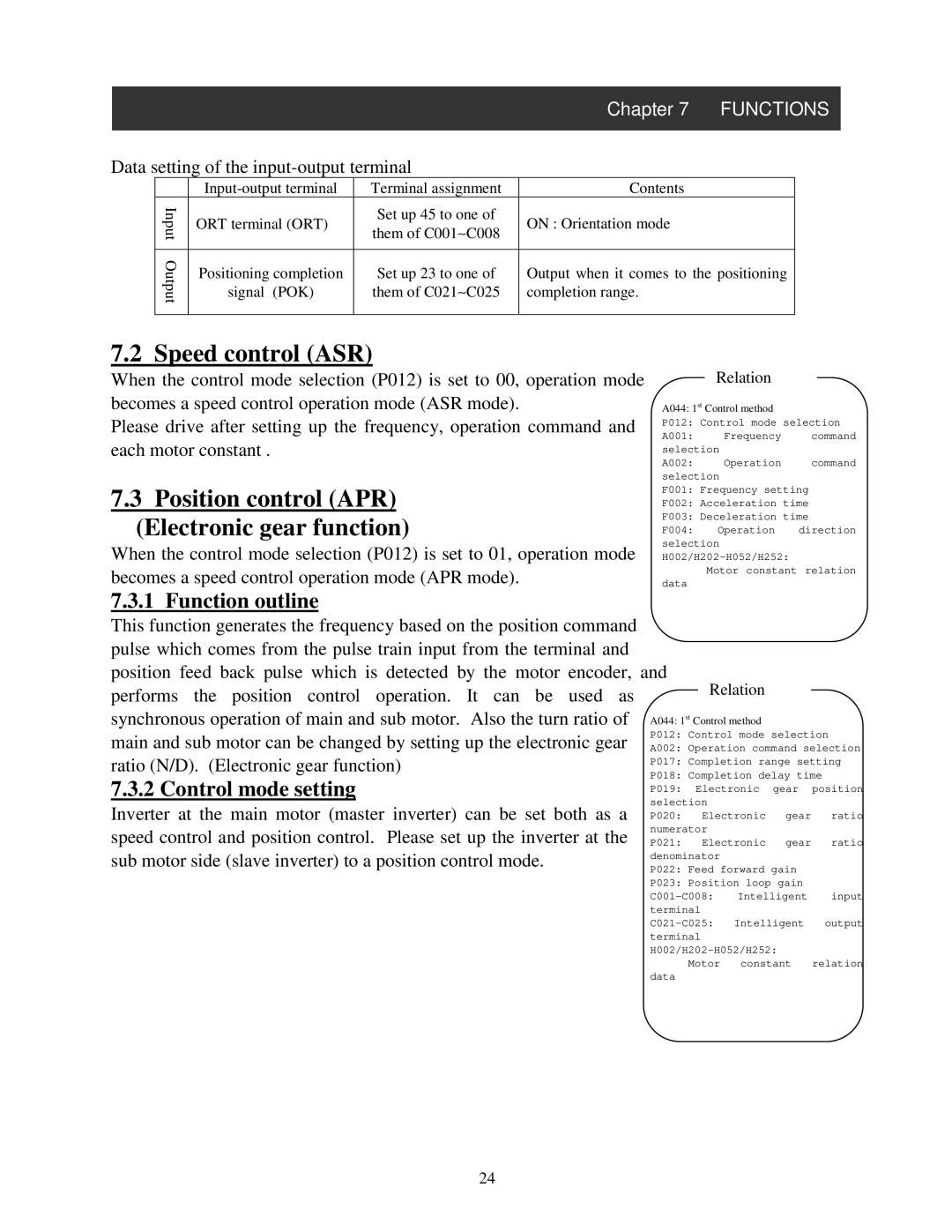
Data setting of the |
|
|
| |||
|
| Terminal assignment | Contents |
|
| |
| Input | ORT terminal (ORT) | Set up 45 to one of | ON : Orientation mode |
|
|
| them of C001∼ C008 |
|
| |||
|
|
|
|
|
|
|
| Output | Positioning completion | Set up 23 to one of | Output when it comes to the positioning |
| |
|
|
| ||||
|
| signal (POK) | them of C021∼ C025 | completion range. |
|
|
|
|
|
|
|
|
|
7.2 Speed control (ASR)
When the control mode selection (P012) is set to 00, operation mode becomes a speed control operation mode (ASR mode).
Please drive after setting up the frequency, operation command and each motor constant .
7.3Position control (APR) (Electronic gear function)
When the control mode selection (P012) is set to 01, operation mode becomes a speed control operation mode (APR mode).
7.3.1 Function outline
Relation
A044: 1st Control method
P012: Control mode selection
A001: Frequency command selection
A002: Operation command selection
F001: Frequency setting
F002: Acceleration time
F003: Deceleration time
F004: Operation direction selection
Motor constant relation
data
This function generates the frequency based on the position command |
|
|
|
|
| |
pulse which comes from the pulse train input from the terminal and |
|
|
|
|
| |
position feed back pulse which is detected by the motor encoder, and |
|
|
|
| ||
| Relation |
|
| |||
performs the position control operation. It can be used as |
|
|
|
| ||
synchronous operation of main and sub motor. Also the turn ratio of | A044: 1st Control method |
|
| |||
main and sub motor can be changed by setting up the electronic gear | P012: Control mode selection | |||||
A002: Operation command selection | ||||||
ratio (N/D). (Electronic gear function) | P017: Completion range setting | |||||
P018: Completion delay time | ||||||
7.3.2 Control mode setting | ||||||
P019: | Electronic | gear | position | |||
| ||||||
Inverter at the main motor (master inverter) can be set both as a | selection |
|
| |||
P020: |
| Electronic | gear | ratio | ||
speed control and position control. Please set up the inverter at the | numerator |
|
| |||
P021: |
| Electronic | gear | ratio | ||
sub motor side (slave inverter) to a position control mode. | denominator |
|
| |||
P022: Feed forward gain |
| |||||
| P023: Position loop gain |
| ||||
| ||||||
| terminal |
|
| |||
| ||||||
| terminal |
|
| |||
|
| |||||
| data | Motor constant | relation | |||
|
|
|
|
| ||
24