Thor CV31
Disclaimer
Trademarks
Patents
Contents
About the User Interface and Installed Applications
Configure the Computer
Manage the Computer
Specifications
Device Settings
Troubleshoot and Maintain the Computer
Warranty Information Web Support
Safety Information
Global Services and Support
Before You Begin
Send Feedback
Who Should Read This Manual
Related Documents
Telephone Support
About the Computer Features
About the Thor CV31
About the Buttons
CV31 Buttons
Callout Button Description
About the Power Options
About the Power Button
Configure the Power Button
Power Button Actions
Power Options Menu
Option Description
About the Ports and Connectors
Configure the Power Options Menu
Page
COM1
CV31 Ports and Connectors
Callout Connector Description
COM3
Callout
About the Status LEDs
Status LED Descriptions
Color Description
How to Supply Power to the CV31
CV31 Power Supply Options for a New Installation
About the Backup Battery
Check the Status of the Backup Battery
Tap Start Settings Control Panel
Disable Backup Battery Charging
How to Mount the CV31
How to Connect a Scanner
USB
About Serial Scanners
Default COM Port Scanner Settings
COM Port Default Scanner Model Default Scanner Settings
Connect a Serial Scanner
How to Connect a Headset
About USB Scanners Connect a USB Scanner
How to Change the Volume
Methods to Change the Volume
Connect an External Keyboard
About External Antennas
Install an External Antenna
About the Bar Code Slot Reader
Configure the Bar Code Slot Reader
Install a microSD Card
Select Enable Scanner Port
About the Computer Features
CV31 Accessories
CV31 Accessories
Accessory Description
Screen
CV31 Accessories
About the User Interface and Installed Applications
About Screen Gestures
About the User Interface
About the Touch Screen
Screen Gestures
Calibrate the Touch Screen
Applications Installed on the Computer
Applications Installed on the Computer
Icon Application Description
Downloadable Applications for the Computer
About HTML5 Browser
About Launcher for Windows
About Intermec Terminal Emulator
About SmartSystems
About the User Interface and Installed Applications
Configure the Computer
How to Configure the Computer
About Intermec Settings on the Computer
Start Intermec Settings
Communications Option Parameters You Can Configure
About the Structure of Intermec Settings
Data Collection Option Parameters You Can Configure
Data Collection Menu
Printer Options Parameters You Can Configure
Device Settings Menu
Device Settings Option Parameters You Can Configure
Printers Menu
License Manager Menu
SmartSystems Information Menu
Device Monitor Menu
Virtual Wedge Menu
Rfid Options Parameters You Can Configure
Core Messaging Service Menu
Core Messaging Service Options Parameters You Can Configure
Rfid Menu
How to Navigate in Intermec Settings
Enable Intermec Settings Password
Tap Menu Enter Password
Restore Default Settings
Hide Menu Items in Intermec Settings
Select Hide Menu Item
Select Start Intermec Settings
Configure the Computer Remotely with SmartSystems
About Bluetooth Communications
About Network Communications
Configure Bluetooth Communications
Connect a Bluetooth Scanner with the Quick Connect Bar Code
Tap Communications Bluetooth
Connect a Bluetooth Scanner with the Wireless Scanning App
Connect to a Bluetooth Printer
About Wireless Security
Load a Certificate
WEP
Select a Funk Security Profile
Select Communications 802.11 Radio Funk Security
For Association, select WPA or WPA2
For 8021x, select TTLS, PEAP, EAP-FAST, or TLS
For Validate Server Certificate, select Yes
For Association, select Open
Configure 802.1x Security with Funk Security
Configure Leap Security with Funk Security
For Association, select Open, WPA, WPA2, or Network EAP
Configure Static WEP Security with Funk Security
Use Open No Security Associations with Funk Security
Configure the Computer
Manage the Computer
How to Manage the Computer in Your Network
How to Manage the Computer with CloneNGo
How to Manage the Computer with SmartSystems
How to Develop and Install Applications
How to Manage the Computer with Third-Party Software
How to Package Your Application
Install Applications with SmartSystems
Install Applications with Microsoft Synchronization Software
Install Applications with a microSD Card
Install Applications with a USB Device
How to Launch Applications Automatically
How to Update the System Software
Update the Computer with SmartSystems
Update the Computer with a microSD Card
Manage the Computer
Troubleshoot and Maintain the Computer
Wi-Fi Connection Problems and Possible Solutions
How to Troubleshoot the Computer
Wi-Fi Connection Problems
Problem Possible Solution
ISpyWiFi Tabs
How to Check Wi-Fi Network Status
802.1x Security Problems
802.1x Security Problems and Possible Solutions
802.1x Security Problems and Possible Solutions
Scanner Settings . Make sure
Problems Reading Bar Codes
Problems Reading Bar Codes
Go to Data Collection
Data Collection Symbologies for
Problems Using the Computer
Problems Using the Computer
Find Your Configuration Number
Call Product Support
Find Your Operating System Version
Reboot the Computer
How to Restart the Computer
Clean the Computer
Reset the Computer
Troubleshoot and Maintain the Computer
Specifications
Specification Measure
Physical and Environmental Specifications
Physical Dimensions
Power and Electrical Specifications
Keyboard Options
Screen Specifications
Bar Code Symbologies
EAN/UPC
Pin Assignments
COM 1 and COM 3 Ports
MSI
COM 1 and COM 3 Port Pin Assignments
Pin Signal Description
USB Port
USB Port Pin Assignments
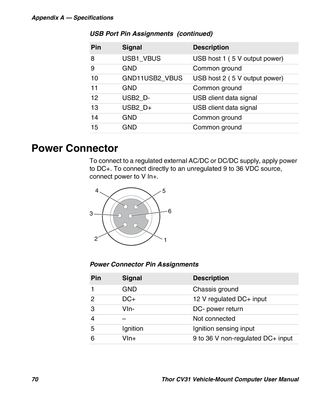
Power Connector
Power Connector Pin Assignments
Device Settings
Data Collection Settings
Default Configuration
Default Configuration
Symbology Settings
Symbology Option Settings
Symbology Option Default Value
Imager Settings
Scanner Settings
Scanner Setting Default Value
Imager Setting Default Value
Decode Security Settings
Rfid Settings
Application Connection Settings
Rfid Module Settings
Reader 1 Settings
Reader 1 Setting Default Value
Rfid Module Setting Default Value
Funk Security Settings
Communications Settings
Radio Settings
Communications
EAP/MD5
Ethernet Adapter Settings
IP Settings Default Value
Cckm
Device Settings
Device Settings
Bluetooth Settings
Power Management Settings
Core Messaging Service Settings
Core Messaging Service
Screen Settings
Device Monitor Settings
Virtual Wedge
Virtual Wedge Settings
Virtual Wedge Setting Default Value
Read Report = Event
Honeywell Scanning & Mobility