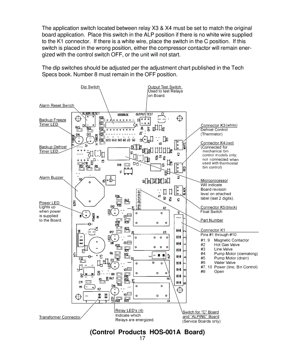
The application switch located between relay X3 & X4 must be set to match the original board application. Place this switch in the ALP position if there is no white wire supplied to the K1 connector. If there is a white wire, place the switch in the C position. If this switch is placed in the wrong position, either the compressor contactor will remain ener- gized with the control switch OFF, or the unit will not start.
The dip switches should be adjusted per the adjustment chart published in the Tech Specs book. Number 8 must remain in the OFF position.
(Control Products HOS-001A Board)
17