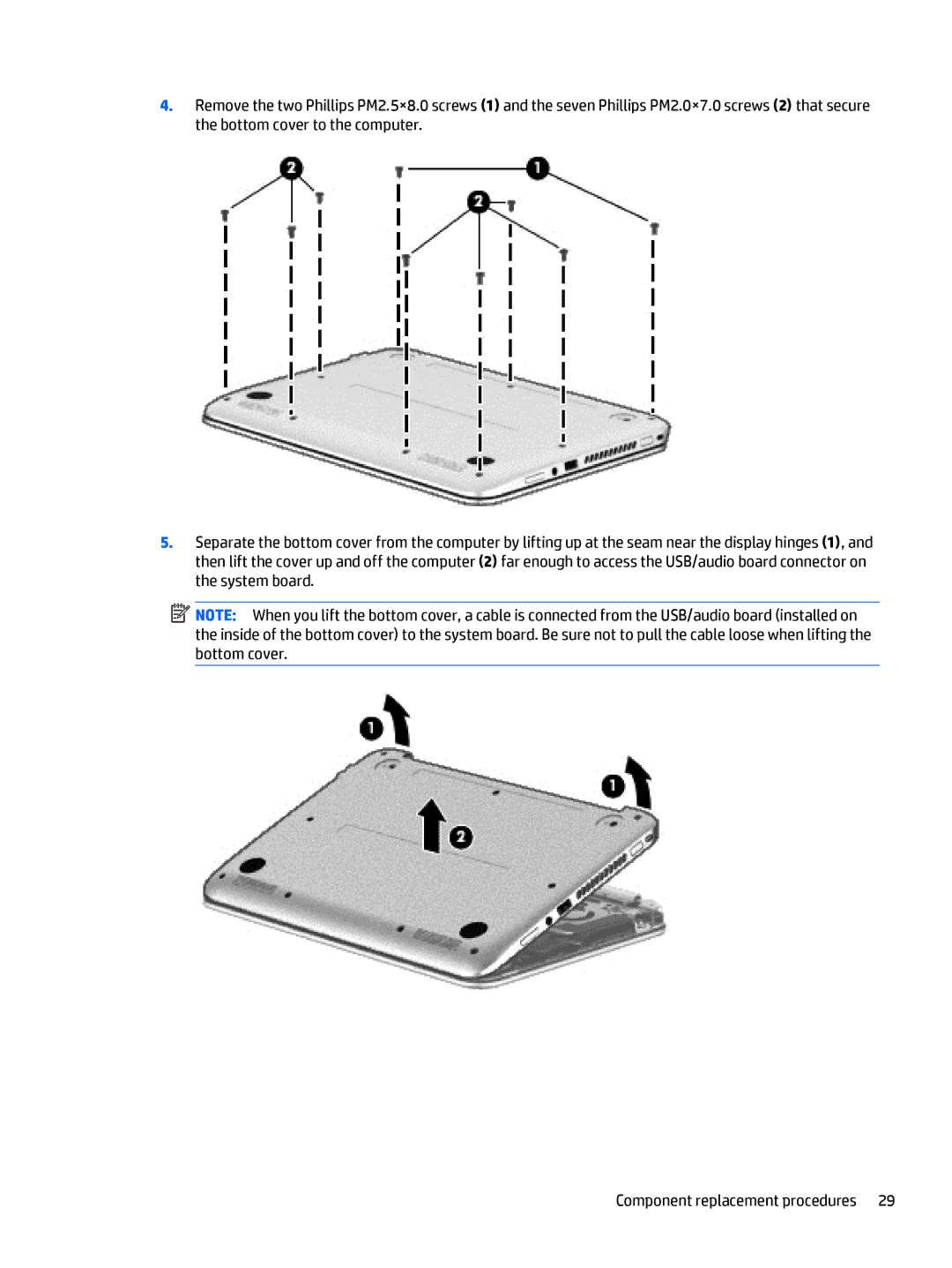
4.Remove the two Phillips PM2.5×8.0 screws (1) and the seven Phillips PM2.0×7.0 screws (2) that secure the bottom cover to the computer.
5.Separate the bottom cover from the computer by lifting up at the seam near the display hinges (1), and then lift the cover up and off the computer (2) far enough to access the USB/audio board connector on the system board.
![]() NOTE: When you lift the bottom cover, a cable is connected from the USB/audio board (installed on the inside of the bottom cover) to the system board. Be sure not to pull the cable loose when lifting the bottom cover.
NOTE: When you lift the bottom cover, a cable is connected from the USB/audio board (installed on the inside of the bottom cover) to the system board. Be sure not to pull the cable loose when lifting the bottom cover.
Component replacement procedures 29