Maintenance & Service Guide
Maintenance & Service Guide
About This Book
Iv About This Book
Table of contents
Removal and replacement procedures
Appendix B Power cord set requirements
Appendix H Statement of Volatility 129 Specifications 130
Product description
Category Description Internal expansion
Power requirements
Ports Rear IO
Front IO
Category Description Operating system Preinstalled
Serviceability End user replaceable part
SoftPaq
Front components
Product features
Rear components
Activating and Customizing the Software
Activating and customizing the software in Windows
Activating the Windows operating system
Downloading Windows 7 updates
Installing or upgrading device drivers
Customizing the monitor display
Click Settings Change PC Settings
Downloading Windows 8 updates
Illustrated parts catalog
Power supply , 180W
Description Spare part number Access panel
Computer Major Components
Front bezel
Item Description Spare part number
Cables
Description Spare part number Front I/O and USB assembly
Misc Parts
Speaker
Sequential Part Number Listing
Drives
Description Spare part number
Spare part Description Number
Thermal material
Illustrated parts catalog
Electrostatic discharge information
Generating static
Preventing electrostatic damage to equipment
Relative Humidity Event 55% 40% 10%
Grounding the work area
Personal grounding methods and equipment
Recommended materials and equipment
Static Shielding Protection Levels
Operating guidelines
Cleaning the Computer Case
General cleaning safety precautions
Cleaning the keyboard
Routine care
Cleaning the monitor
Service considerations
Cleaning the mouse
Power supply fan
Tools and software Requirements
Cables and connectors
Screws
Hard Drives
Lithium coin cell battery
Serial ATA Hard Drive Characteristics
Sata hard drives
Smart ATA drives
Sata hard drive cables
Cable management
Sata data cable
Removal and replacement procedures
Serviceability features
Preparation for disassembly
Description Spare part number Access panel 674373-001
Access panel
Description Spare part number Front bezel 751588-001
Front bezel
DDR3L-SDRAM SODIMMs
Memory
Description Socket Color Insertion Order
Populating Dimm sockets
Removing memory modules
Expansion cards
Page
Cable management
Cable connections
Connector Name Connector Color Description
Drives
Installing additional drives
Drive System Board Label Color
System board drive connections
Removing an optical drive
Removing a hard drive
Front I/O and USB panel housing assembly
Page
Remove the optical drive Removing an optical drive on
Power switch/LED assembly
Page
Description Spare part number Speaker 751593-001
Speaker
Page
Page
Power supply
Page
System board
Page
Battery
Page
Computer Setup F10 Utilities
Computer Setup F10 Utility
Using Computer Setup F10 Utilities
Computer Setup-File
Configuration
Computer Setup-Storage
Option Description Device
Storage Options Sata Emulation
Boot Order
Shortcut to Temporarily Override Boot Order
DPS Self-test
Computer Setup-Security
Computer Setup-Power
Option Power-On Options
Computer Setup-Advanced
Bios Power-On Onboard Devices Bus Options
Device Options
Power cord set requirements
Japanese power cord requirements
General requirements
Country Accrediting Agency
Country-specific requirements
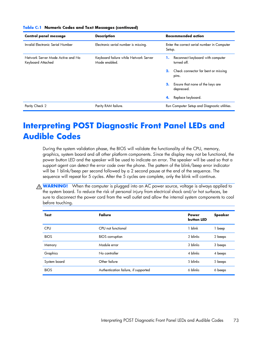
Post Error Messages
Control panel message Description Recommended action
Post Numeric Codes and Text Messages
Control panel message Description
Verify monitor is attached and turned
Reseat CPU or chassis fan
Sata Emulation to IDE, and select File
Change Storage Storage Options
Save Changes and Exit. Reenter
Drivelock Security. For each listed
Appendix C Post Error Messages
If the error persists, update to the latest
Bios version and ME firmware version
Bios
Test Failure Power Speaker Button LED
Cmos
Password Security and Resetting
Clearing and Resetting the Cmos
Resetting the Password Jumper
Page
Safety and comfort Before you call for technical support
Troubleshooting without diagnostics
Helpful hints
Page
Solving general problems
Computer date and time display is incorrect Cause Solution
Select Control Panel
Cannot remove computer cover or access panel Cause Solution
There is no sound or sound volume is too low Cause Solution
Poor performance Cause Solution
Advanced Device Options
Run
Go to Start All Programs Accessories
All apps icon
Under Windows System, click Run
Open the access panel, press the power button, and see
Power supply shuts down intermittently Cause Solution
Solving power problems
Hard drive error occurs Cause Solution
Solving hard drive problems
Tools tab. Under Error-checking click Check Now
Error checking click Check
Drive not found identified Cause Solution
Disk transaction problem Cause Solution
Advanced Power-On Options
Nonsystem disk/NTLDR missing message Cause Solution
Storage Boot Order
Computer will not boot from hard drive Cause Solution
Device Configuration
Computer seems to be locked up Cause Solution
Can not write to the media card Cause Solution
Solving media card reader problems
Blank screen no video Cause Solution
Solving display problems
List, then under Appearance and Personalization
Select Adjust screen resolution
Dim characters Cause Solution
Select ImageControl/ Horizontal Position or Vertical
Image is not centered Cause Solution
Out of Range displays on screen Cause Solution
Support
Certain typed symbols do not appear correct Cause Solution
Solving audio problems
Sound cuts in and out Cause Solution
Device Security System Audio
Control Panel, and then select Device Manager
Line-in jack is not functioning properly Cause Solution
Control Panel , and then select Device Manager
Solving printer problems
Printer will not turn on Cause Solution
Solving keyboard and mouse problems
Printer prints garbled information Cause Solution
Printer will not print Cause Solution
Enter
Table E-1Solving Hardware Installation Problems
Solving Hardware Installation Problems
Security USB Security
Computer will not start Cause Solution
102 Appendix E Troubleshooting without diagnostics
Solving Network Problems
Manager
Network status link light never flashes Cause Solution
Diagnostics reports a failure Cause Solution
New network card will not boot Cause Solution
Solving memory problems
Out of memory error Cause Solution
Memory count during Post is wrong Cause Solution
Insufficient memory error during operation Cause Solution
Solving processor problems
Poor performance is experienced Cause Solution
Cause Solution
Security Network Boot
Solving CD-ROM and DVD problems
Cannot eject compact disc tray-load unit Cause Solution
Movie will not play in the DVD drive Cause Solution
Solving USB flash drive problems
USB flash drive not found identified Cause Solution
System will not boot from USB flash drive Cause Solution
Solving front panel component problems
Solving Internet access problems
Unable to connect to the Internet Cause Solution
Click Internet Options
Select Start Control Panel
ROM issue Post error has occurred
Solving software problems
Verify that the software is certified by Microsoft for your
HP PC Hardware Diagnostics
Why run HP PC Hardware Diagnostics
How to access and run HP PC Hardware Diagnostics
Downloading HP PC Hardware Diagnostics to a USB device
Creating recovery media and backups
System backup and recovery
Using Reset when the system is not responding
Restoring and recovering using Windows tools
Recovery using the Windows recovery USB flash drive
Creating recovery media
Backing up, restoring, and recovering in Windows
Click All Programs
Creating recovery discs
Backing up your information
System Restore
System Recovery when Windows is responding
System Recovery
System Recovery when Windows is not responding
Page
Select Install now
Statement of Volatility
MT Specifications
Specifications
Cmos
Index
Installing
Sata