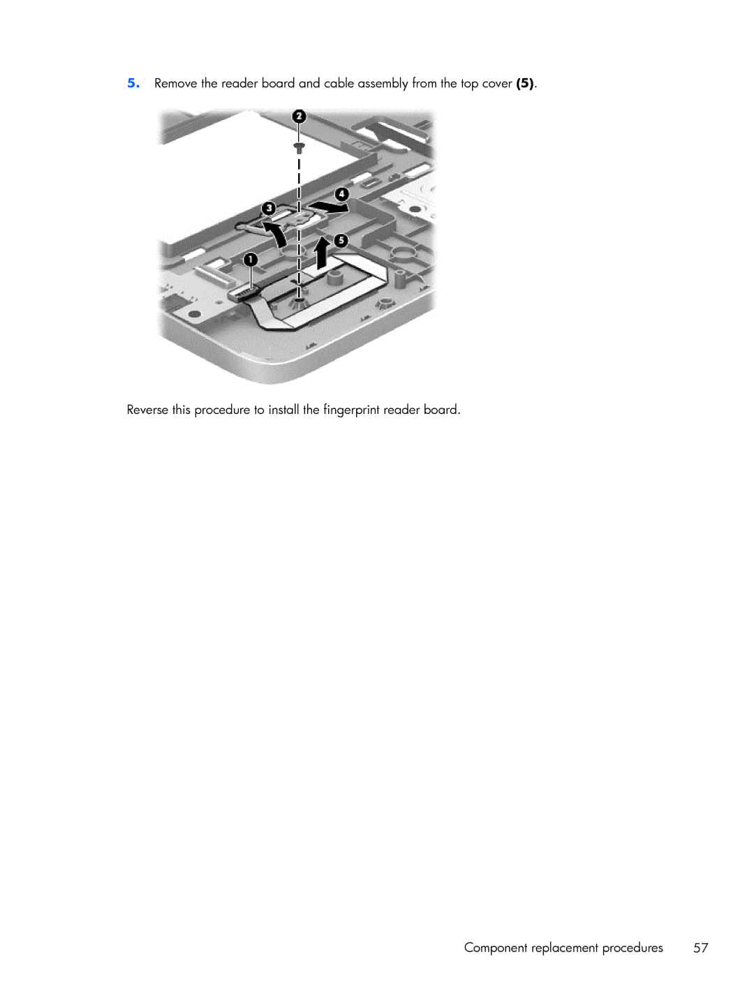
Manuals
/
HP
/
Computer Equipment
/
Laptop
HP
430 G1 E3U87UTABA manual Remove the reader board and cable assembly from the top cover
Models:
430 G1 E3U87UTABA
1
67
139
139
Download
139 pages
27 Kb
64
65
66
67
68
69
70
71
<
>
Specs
Install
FAQ
Important Notice about Customer Self-Repair Parts
Removal and replacement procedures preliminary requirements
Dimension
Maintenance
Wireless
Computer Setup BIOS and Advanced System Diagnostics
Using Computer Setup
Page 67
Image 67
5.
Remove the reader board and cable assembly from the top cover
(5)
.
Reverse this procedure to install the fingerprint reader board.
Component replacement procedures
57
Page 66
Page 68
Page 67
Image 67
Page 66
Page 68
Contents
HP ProBook 430 G1 Notebook PC
Maintenance and Service Guide
Product notice
Important Notice about Customer Self-Repair Parts
iv Important Notice about Customer Self-Repair Parts
Safety warning notice
vi Safety warning notice
External component identification
Table of contents
Removal and replacement procedures preliminary requirements
Product description
Computer Setup BIOS and Advanced System Diagnostics
Removal and replacement procedures for Customer Self-Repair parts
8 Specifications
Power cord set requirements
9 Backup and recovery in Windows
10 Backup and recovery in Windows
11 Backup and Recovery in SLED
Product Name
1 Product description
Category
Description
Category
Wireless
Integrated WLAN options by way of wireless module
Integrated WWAN options by way of wireless module
Category
Bluetooth combo card
Power requirements
Preinstalled
Web-only support
Restore Media
Serviceability
CategoryDescription
WLAN module WWAN module, SIM Keyboard
CategoryDescription
Component
2 External component identification
Display - Windows models
Send and receive wireless signals to communicate with wireless
select the HP Support Assistant app
Component
Description
Webcam
Description
Display - SLED models
Send and receive wireless signals to communicate with wireless
Component
Component
TouchPad
Description
Component
Lights select models only
Description
Component
Buttons and fingerprint reader select models only
Description
Component
Keys
Component
Description
num lk key
Front
Component
Description
Component
Left
Description
Description
Right
Regulatory, Safety, and Environmental Notices . To access
Component
Component
Bottom
governmental agency that regulates wireless devices in
restore computer functionality, and then contact support
Service tag
Service tag and PCID label
Chapter 2 External component identification
PCID label
Computer major components
3 Illustrated parts catalog
Spare part
Power button board includes cable
RTC battery
Description
Spare part
Speaker assembly
Service door
Description
Display bezel
Display components
Description
Spare part number
Cable Kit
Cable Kit
Item Description
Spare part number
Spare part number
Mass storage devices
Chapter 3 Illustrated parts catalog
Description
Spare part number
Miscellaneous parts
Power cords
Description
number
Sequential part number listing
Spare part
Description
number
Sequential part number listing
Spare part
Description
number
Chapter 3 Illustrated parts catalog
Spare part
Description
flag
Spare part
Description
number
Plastic parts
4 Removal and replacement procedures preliminary requirements
Service considerations
Tools required
Drive handling
Cables and connectors
Electrostatic discharge damage
Grounding guidelines
Workstation guidelines
Packaging and transporting guidelines
Material
Equipment guidelines
Voltage protection level
Component replacement procedures
5 Removal and replacement procedures for Customer Self- Repair parts
Battery
3. Remove the battery 2 from the computer
Remove the battery
1. Position the computer upside-down on a flat surface
Keyboard
7. Release the ZIF connector 1 by lifting the latch
Component replacement procedures
9. Remove the keyboard Reverse this procedure to install the keyboard
Hard drive
Component replacement procedures
Reverse this procedure to reassemble and install the hard drive
Service door
Page
Memory modules
WWAN module
Component replacement procedures
Reverse this procedure to install the WWAN module
Figure 5-1 Removing the WWAN module
WLAN/Bluetooth combo card
Component replacement procedures
Reverse this procedure to install the WLAN module
Component replacement procedures
Top cover
b. Keyboard see Keyboard on page c. Hard drive see Hard drive on page
a. Service door see Service door on page
5. Position the computer upright with the front toward you
4. Disconnect the audio board cable from the system board
Component replacement procedures
1 Power button cable 2 Touchpad board cable 3 Function board cable
7. Disconnect the following cables from the system board
3 Touchpad board cable 4 Power button board cable
Reverse this procedure to install the top cover
1 Function board cable 2 Fingerprint reader board cable
b. Keyboard see Keyboard on page c. Top cover see Top cover on page
RTC battery
a. Service door see Service door on page
Fingerprint reader board
b. Keyboard see Keyboard on page c. Top cover see Top cover on page
Reverse this procedure to install the fingerprint reader board
5. Remove the reader board and cable assembly from the top cover
Component replacement procedures
a. Service door see Service door on page
Audio board
b. Keyboard see Keyboard on page c. Top cover see Top cover on page
a. Service door see Service door on page
Function board
b. Keyboard see Keyboard on page c. Top cover see Top cover on page
a. Service door see Service door on page
Power button board
b. Keyboard see Keyboard on page c. Top cover see Top cover on page
Component replacement procedures
Reverse this procedure to install the power button board
b. Keyboard see Keyboard on page c. Top cover see Top cover on page
Speaker assembly
d. System board see System board on page
a. Service door see Service door on page
Component replacement procedures
Reverse this procedure to install the speaker assembly
c. WWAN module see WWAN module on page
Display assembly
b. WLAN module see WLAN/Bluetooth combo card on page
f. Power connector cable see Power connector cable on page
Component replacement procedures
8. Lift the bracket 2 up and out of the base enclosure
10. Lift the display assembly straight up and remove it
2 from the bottom corners of the display bezel
6 of the bezel until it disengages from the display enclosure
The bezel is available using spare part number
The webcam module is available using spare part number
Component replacement procedures
Page
Reverse this procedure to reassemble and install the display assembly
Display hinges are available using spare part number
Component replacement procedures
b. Keyboard see Keyboard on page c. Top cover see Top cover on page
Power connector cable
d. Display see Display assembly on page
a. Service door see Service door on page
System board
b. Hard drive see Hard drive on page c. Keyboard see Keyboard on page
d. Top cover see Top cover on page
Memory module see Memory modules on page
WLAN module see WLAN/Bluetooth combo card on page
WWAN module see WWAN module on page
Component replacement procedures
Reverse this procedure to install the system board
b. Hard drive see Hard drive on page c. Keyboard see Keyboard on page
Heat sink
e. System board see System board on page
a. Service door see Service door on page
Component replacement procedures
Reverse this procedure to install the heat sink
4. Lift the heat sink off the system board
Starting Computer Setup
7 Computer Setup BIOS and Advanced System Diagnostics
Windows 7 - Computer Setup BIOS and Advanced System Diagnostics
Using Computer Setup
Restoring factory settings in Computer Setup
Navigating and selecting in Computer Setup
Downloading SoftPaqs to update the BIOS
Updating the BIOS
BIOS management using system diagnostics
Determining the BIOS version
Using f10 setup to update the BIOS
Downloading a BIOS update
BIOS Setup Menu
1. Select Start Help and Support Maintain
Security menu
Using Advanced System Diagnostics
Diagnostics menu
Main menu
Page
Navigating and selecting in Computer Setup
Windows 8 - Computer Setup BIOS and Advanced System Diagnostics
Using Computer Setup
Starting Computer Setup
Updating the BIOS
Restoring factory settings in Computer Setup
Downloading a BIOS update
Determining the BIOS version
About the boot device order
Using MultiBoot
Choosing MultiBoot preferences
Dynamically choosing a boot device using the f9 prompt
Setting a new boot order in Computer Setup
Setting a MultiBoot Express prompt
Entering MultiBoot Express preferences
Using System Diagnostics
Windows 8 - Computer Setup BIOS and Advanced System Diagnostics
To start System Diagnostics
Navigating and selecting in Computer Setup
SLED - Computer Setup BIOS and Advanced System Diagnostics
Starting Computer Setup
Using Computer Setup
Restoring factory settings in Computer Setup
Updating the BIOS
Downloading a BIOS update
Determining the BIOS version
Using Advanced System Diagnostics
Input power
8 Specifications
Computer specifications
Dimensions
Metric
33.8-cm 13.3-in, HD display specifications
Metric
320-GB
Hard drive specifications
Dimensions
Operating temperature
To access Device Manager in Windows
Specification information in Device Manager
To access Device Manager in Windows
1. Select Start Computer System properties
9 Backup and recovery in Windows
2. Select Driver DVD or Windows DVD
Creating recovery media with HP Recovery Disc Creator
Creating recovery media
Backing up your information
1. Select Start All Programs Maintenance Backup and Restore
Performing a system recovery
Using the Windows recovery tools
1. Select Start All Programs Maintenance Backup and Restore
4. Select Startup Repair
Using f11 recovery tools
6. Select Repair your computer
Using a Windows 7 operating system DVD purchased separately
with File History
10 Backup and recovery in Windows
Backing up your information
Using the Windows recovery tools
Performing a system recovery
Using f11 recovery tools
Using Windows Refresh for quick and easy recovery
Using Windows 8 operating system media purchased separately
2. Click Settings
Remove everything and reinstall Windows
2. Click Settings
Using HP Software Setup
Creating backups
11 Backup and Recovery in SLED
Backing up your information
1. Select Computer More Applications
1. Select Computer More Applications Tools Backup Manager Restore
Performing a system recovery
Restore?
USB Recovery option select models only
2. Select Computer More applications Tools Create Recovery USB
Remove everything and reinstall SLED
12 Statement of Volatility
a. Hard Disk Drive HDD
h. Select the File menu, then Save Changes and Exit
b. Solid State Drive SSD
Non Volatile
Non-volatile memory usage
What is the
power is
Amount
What is the
power is
Non Volatile
Questions and answers
Requirements for all countries and regions
13 Power cord set requirements
Applicable note number
Requirements for specific countries and regions
Country/region
Accredited agency
Applicable note number
120 Chapter 13 Power cord set requirements
Country/region
Accredited agency
14 Recycling
Battery
Display
3. Remove the display bezel
Perform the following steps to disassemble the display assembly
122 Chapter 14 Recycling
7. Position the display panel assembly upside-down
6. Remove the display panel assembly 2 from the display enclosure
Display
14. Position the display panel right-side up
10. Remove the display panel frame 2 from the display panel
12. Lift the top edge of the backlight cover 2 and swing it outward
13. Remove the backlight cover
17. Remove the backlight frame from the display panel
16. Position the display panel upside-down
Display
23. Remove the LCD panel 24. Recycle the LCD panel and backlight
18. Remove the backlight from the backlight frame
19. Disconnect the display panel cable 1 from the LCD panel
21. Release the LCD panel 3 from the display rear panel
Index
K keyboard
J jacks