Manuals
/
HP
/
Computer Equipment
/
Laptop
HP
430 G1 E3U93UTABA, 430 G1 E3U85UTABA
manual
Illustrated parts catalog, Computer major components
Models:
430 G1 E3U85UTABA
430 G1 E3U93UTABA
430 G1 E3U87UTABA
1
29
139
139
Download
139 pages
27 Kb
26
27
28
29
30
31
32
33
<
>
Specifications
Install
FAQ
Bluetooth
Diagnostics menu
Using Computer Setup
Cables and connectors
Determining the Bios version
Speaker assembly
RTC battery
Page 29
Image 29
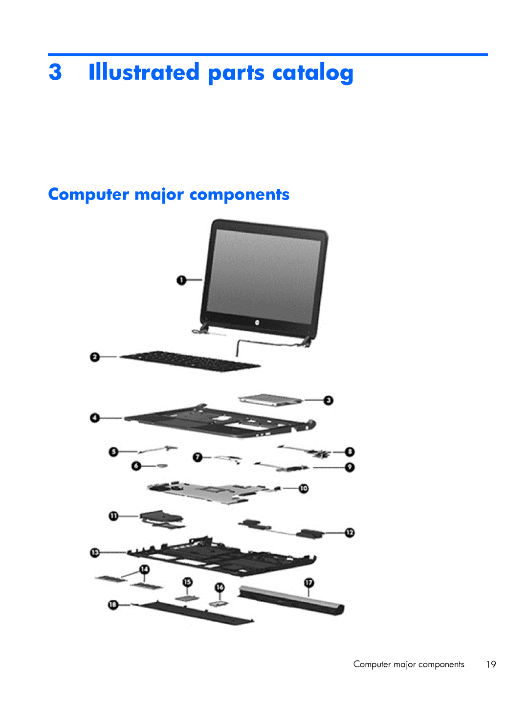
3 Illustrated parts catalog
Computer major components
Computer major components
19
Page 28
Page 30
Page 29
Image 29
Page 28
Page 30
Contents
HP ProBook 430 G1 Notebook PC
Product notice
Important Notice about Customer Self-Repair Parts
Iv Important Notice about Customer Self-Repair Parts
Safety warning notice
Vi Safety warning notice
Table of contents
Computer Setup Bios and Advanced System Diagnostics
Specifications
Backup and recovery in Windows 103
Backup and recovery in Windows
Backup and Recovery in Sled 109
Power cord set requirements 118
Chipset
Product description
Graphics
Panel
Integrated Wwan options by way of wireless module
Wireless Integrated Wlan options by way of wireless module
Category Description Hard drives
Optical drives
Power requirements
Bluetooth combo card
Operating system Preinstalled
Category Description
Serviceability End-user replaceable parts
Restore Media
CategoryDescription
Web-only support
Wlan module Wwan module, SIM Keyboard
Display Windows models
External component identification
Component Description Wlan antennas 2* select models only
Local area networks Wlan
Select the HP Support Assistant app
Component Description
Display Sled models
TouchPad
Top
Sled
Lights select models only
Buttons and fingerprint reader select models only
Fn key
Keys
Num lk key
Front
Left
Right
Regulatory, Safety, and Environmental Notices . To access
Assistant app
Bottom
Service tag
Service tag and Pcid label
Pcid label
Computer major components
Illustrated parts catalog
RTC battery
Power button board includes cable
Description Spare part Number
Hard drive
Service door
Speaker assembly
Wwan modules
Wlan module
Display components
Item Description Spare part number Cable Kit 727757-001
Cable Kit
Description Spare part number Hard drives
Mass storage devices
Miscellaneous parts
Number Flag
Sequential part number listing
Sequential part number listing
Illustrated parts catalog
Replacement thermal material
Service considerations
Removal and replacement procedures preliminary requirements
Tools required
Plastic parts
Drive handling
Cables and connectors
Electrostatic discharge damage
Grounding guidelines
Packaging and transporting guidelines
Material Use Voltage protection level
Equipment guidelines
Battery
Component replacement procedures
Page
Description Spare part number Keyboard 727765-xx1
Keyboard
Page
Page
Hard drive
Page
Page
Description Spare part number Service door 727756-001
Service door
SIM
Memory modules
Wwan module
Page
WLAN/Bluetooth combo card
Page
Top cover
Page
Page
Page
Page
Description Spare part number RTC battery 684248-001
RTC battery
Fingerprint reader board
Page
Description Spare part number Audio board 727759-001
Audio board
Description Spare part number Function board 727768-001
Function board
Power button board
Page
Description Spare part number Speaker assembly 727761-001
Speaker assembly
Page
Display assembly
Page
Page
Page
Page
Page
Power connector cable
System board
Page
Page
Description Spare part number Heat sink 727766-001
Heat sink
Page
Using Computer Setup
Computer Setup Bios and Advanced System Diagnostics
Navigating and selecting in Computer Setup
Bios management using system diagnostics
Downloading SoftPaqs to update the Bios
Determining the Bios version
Using f10 setup to update the Bios
Select Start Help and Support Maintain
Downloading a Bios update
Diagnostics menu
Using Advanced System Diagnostics
Main menu
Security menu
Page
Using Computer Setup
Restoring factory settings in Computer Setup
Determining the Bios version
About the boot device order
Using MultiBoot
Setting a MultiBoot Express prompt
Setting a new boot order in Computer Setup
Dynamically choosing a boot device using the f9 prompt
Entering MultiBoot Express preferences
Using System Diagnostics
Page
Starting Computer Setup
Sled Computer Setup Bios and Advanced System Diagnostics
Updating the Bios
Determining the Bios version
Using Advanced System Diagnostics
Computer specifications
Specifications
Metric
33.8-cm 13.3-in, HD display specifications
Hard drive specifications
To access Device Manager in Windows
Specification information in Device Manager
Backup and recovery in Windows
Backing up your information
Creating recovery media with HP Recovery Disc Creator
Creating recovery media
Using the Windows recovery tools
Performing a system recovery
Using f11 recovery tools
Select Repair your computer
Using a Windows 7 operating system DVD purchased separately
With File History
Performing a system recovery
Using f11 recovery tools
Using Windows Refresh for quick and easy recovery
Using Windows 8 operating system media purchased separately
Click Settings
Remove everything and reinstall Windows
Using HP Software Setup
Creating backups
Backup and Recovery in Sled
Select Computer More Applications
Select Computer More applications Tools Create Recovery USB
USB Recovery option select models only
Remove everything and reinstall Sled
Statement of Volatility
Select the File menu, then Save Changes and Exit
Cmos
Non-volatile memory usage
Present only Settings
Questions and answers
Requirements for all countries and regions
Power cord set requirements
Country/region Accredited agency Applicable note number
Requirements for specific countries and regions
Power cord set requirements
Display
Battery
Recycling
Page
Page
Page
Page
Page
Index
Bios
Keyboard
Jacks
Sled
Top
Page
Image
Contents