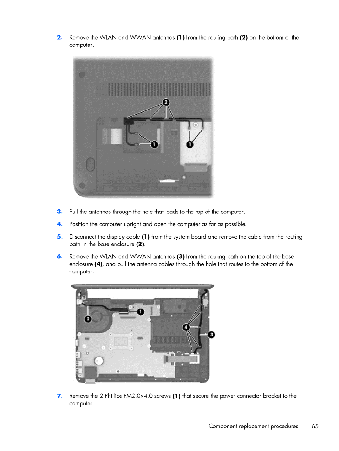
2.Remove the WLAN and WWAN antennas (1) from the routing path (2) on the bottom of the computer.
3.Pull the antennas through the hole that leads to the top of the computer.
4.Position the computer upright and open the computer as far as possible.
5.Disconnect the display cable (1) from the system board and remove the cable from the routing path in the base enclosure (2).
6.Remove the WLAN and WWAN antennas (3) from the routing path on the top of the base enclosure (4), and pull the antenna cables through the hole that routes to the bottom of the computer.
7.Remove the 2 Phillips PM2.0×4.0 screws (1) that secure the power connector bracket to the computer.
Component replacement procedures | 65 |