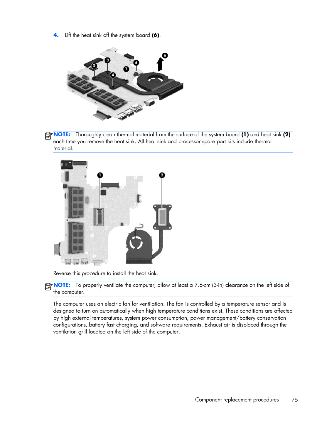
4.Lift the heat sink off the system board (6).
![]()
![]()
![]()
![]() NOTE: Thoroughly clean thermal material from the surface of the system board (1) and heat sink (2) each time you remove the heat sink. All heat sink and processor spare part kits include thermal material.
NOTE: Thoroughly clean thermal material from the surface of the system board (1) and heat sink (2) each time you remove the heat sink. All heat sink and processor spare part kits include thermal material.
Reverse this procedure to install the heat sink.
![]()
![]()
![]()
![]() NOTE: To properly ventilate the computer, allow at least a
NOTE: To properly ventilate the computer, allow at least a
The computer uses an electric fan for ventilation. The fan is controlled by a temperature sensor and is designed to turn on automatically when high temperature conditions exist. These conditions are affected by high external temperatures, system power consumption, power management/battery conservation configurations, battery fast charging, and software requirements. Exhaust air is displaced through the ventilation grill located on the left side of the computer.
Component replacement procedures | 75 |