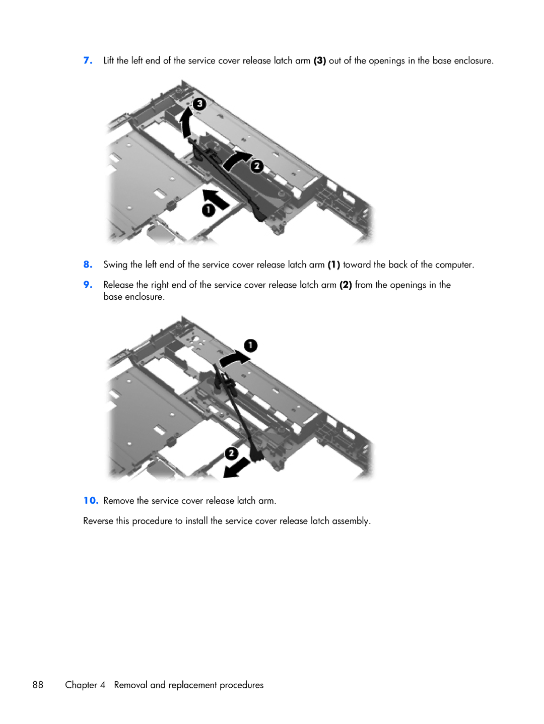
7.Lift the left end of the service cover release latch arm (3) out of the openings in the base enclosure.
8.Swing the left end of the service cover release latch arm (1) toward the back of the computer.
9.Release the right end of the service cover release latch arm (2) from the openings in the base enclosure.
10.Remove the service cover release latch arm.
Reverse this procedure to install the service cover release latch assembly.
88 | Chapter 4 Removal and replacement procedures |
