E700 specifications
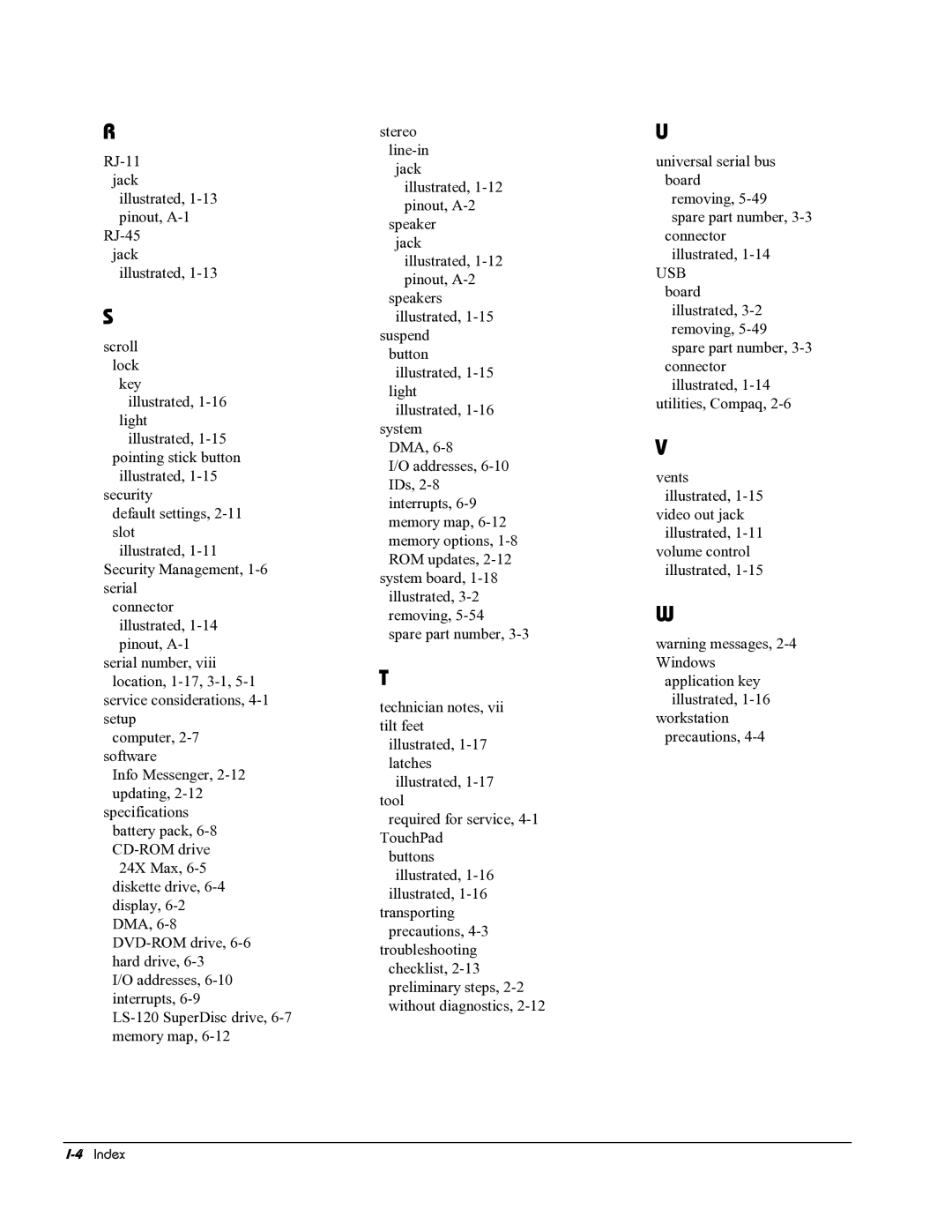
The HP E700 is a powerful, versatile printing solution designed to meet the demands of modern businesses. With its robust feature set, this printer efficiently handles high-volume printing tasks, making it an ideal choice for offices that require both speed and quality.One of the standout features of the HP E700 is its impressive print speed. Capable of producing up to 50 pages per minute, this printer ensures that large documents are printed quickly, minimizing waiting times and maximizing productivity. The first page out time is equally commendable, typically taking less than 7 seconds, allowing users to start printing almost instantaneously.
In terms of print quality, the E700 does not disappoint. This printer utilizes HP’s renowned JetIntelligence technology, which combines precision toner formulation and advanced print resolution. Users can expect sharp text and vivid color graphics, making the E700 suitable for a variety of printing needs, from professional reports to marketing materials.
The HP E700 is designed for ease of use, featuring a user-friendly touchscreen interface that simplifies navigation and setting adjustments. Wireless connectivity options, including Wi-Fi Direct and NFC, enable seamless printing from mobile devices and laptops, allowing users to print documents from virtually anywhere within the office.
Security is a top priority for the E700, which includes advanced features to protect sensitive data. HP’s security technologies safeguard against unauthorized access and ensure that confidential information remains protected throughout the printing process. Features like secure boot, firmware integrity check, and optional secure printing add layers of security, making it a reliable choice for businesses concerned with confidentiality.
Moreover, the E700 is designed with sustainability in mind. HP’s innovative energy-efficient technologies help to reduce power consumption, and the printer is compatible with high-yield toner cartridges, which significantly lower the cost-per-page while reducing waste.
The E700 also offers flexible paper handling options, accommodating various media sizes and types. With multiple input trays and an automatic duplexing feature, it simplifies the printing process and contributes to overall efficiency.
In conclusion, the HP E700 stands out as a multifunctional printer that combines speed, quality, security, and environmental responsibility, making it a perfect fit for any demanding office environment seeking reliable printing solutions.
