Installing the Switch 208/224
Installation Steps
6. Connect the Network Cables
Using RJ-45 Connectors (10 Mbit/s and 100 Mbit/s ports)
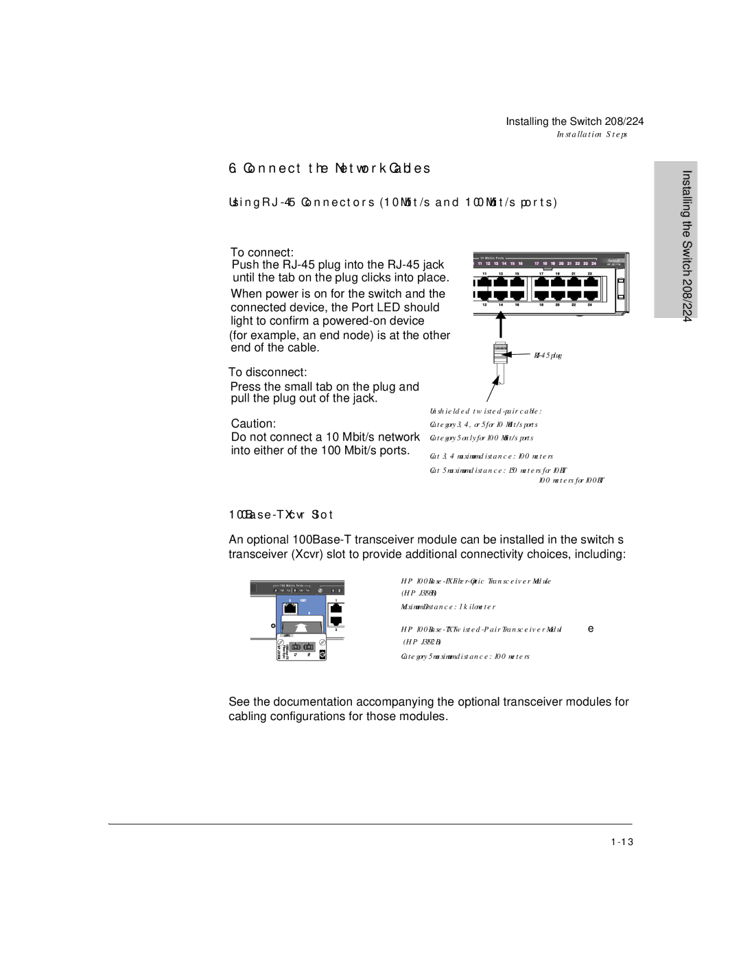
To connect:
Push the
When power is on for the switch and the connected device, the Port LED should light to confirm a
(for example, an end node) is at the other end of the cable.
![]()
![]()
Installing the Switch 208/224
To disconnect:
Press the small tab on the plug and pull the plug out of the jack.
Caution:
Do not connect a 10 Mbit/s network into either of the 100 Mbit/s ports.
Unshielded
Cat 3, 4 maximum distance: 100 meters
Cat 5 maximum distance: 150 meters for 10BT 100 meters for 100BT
100Base-T Xcvr Slot
An optional
HP
Maximum Distance: 1 kilometer
HP
Category 5 maximum distance: 100 meters
See the documentation accompanying the optional transceiver modules for cabling configurations for those modules.