HP J3175A, J3177A manual Insert a screw into the top hole of a close 0.5-inch

Models: J3175A J3177A

1 62
Download 62 pages 8.73 Kb
Page 17
Image 17

Installing the Switch 208/224

Installation Steps

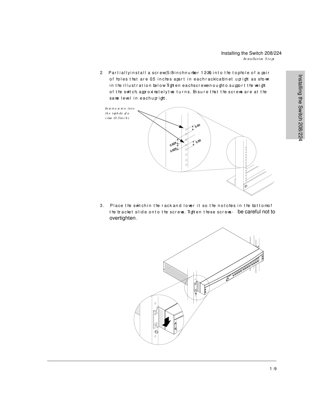
2.Partially install a screw (5/8-inch number 12-24) into the top hole of a pair of holes that are 0.5 inches apart in each rack/cabinet upright as shown in the illustration below. Tighten each screw enough to support the weight of the switch, approximately two turns. Ensure that the screws are at the same level in each upright.

Insert a screw into the top hole of a close (0.5-inch)

3.Place the switch in the rack and lower it so the notches in the bottom of the bracket slide onto the screws. Tighten these screws-be careful not to overtighten.

Installing the Switch 208/224

1-9

Page 17
Image 17
HP J3175A, J3177A manual Insert a screw into the top hole of a close 0.5-inch