Switch 208/224
Installing the Switch 208/224
Installation Steps
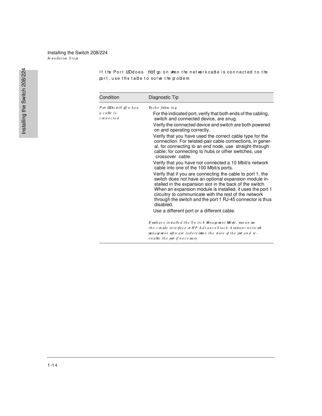
If the Port LED does not go on when the network cable is connected to the port, use this table to solve the problem:
Condition | Diagnostic Tip |
|
|
Installing the
Port LED is still off when a cable is
connected
Try the following:
•For the indicated port, verify that both ends of the cabling, switch and connected device, are snug.
•Verify the connected device and switch are both powered on and operating correctly.
•Verify that you have used the correct cable type for the connection. For
•Verify that you have not connected a 10 Mbit/s network cable into one of the 100 Mbit/s ports.
•Verify that if you are connecting the cable to port 1, the switch does not have an optional expansion module in- stalled in the expansion slot in the back of the switch.
When an expansion module is installed, it uses the port 1 circuitry to communicate with the rest of the network through the switch and the port 1
•Use a different port or a different cable.
If you have installed the Switch Management Module, you can use the console interface or HP AdvanceStack Assistant network management software to determine the state of the port and re- enable the port if necessary.
