The following is a list of component requirements for grounding and bonding:
•Grounding of the HP POD 240e NA must comply with the requirements of Article 250 of the NEC, NFPA
•Bonding of the piping systems and any exposed structural steel, installed to support the HP POD 240e NA, must be in accordance with NEC (NA) and with local and regional regulations (IEC for EMEA and APJ).
Grounding feature | Specification |
|
|
Grounding electrode | • The grounding electrode conductor connection bus pad is located on the outside of |
conductor pad | the HP POD 240e NA on the cold aisle adjacent to the power cabinet. |
| • The grounding pad must be connected to the grounding electrode system or |
| building steel in accordance with Article 250 of the NEC or equivalent regional |
| regulations. |
|
|
Grounding lugs | • Grounding lugs cannot be attached to any painted surface. |
| • Grounding lugs must be |
| grounding. |
|
|
Ground rod system or | You must provide an effective grounding system with a ground rod or a ground well. |
ground well |
|
IMPORTANT: Before installing the HP POD 240e NA, consult your local AHJ for applicable regulations and to review
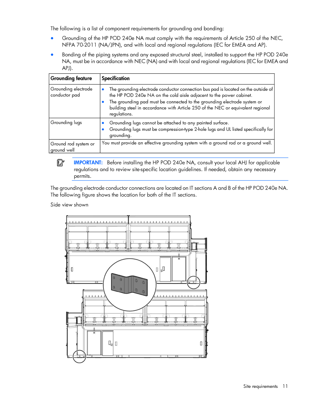
The grounding electrode conductor connections are located on IT sections A and B of the HP POD 240e NA. The following figure shows the location for both of the IT sections.
Side view shown