Overview
Rear Panels
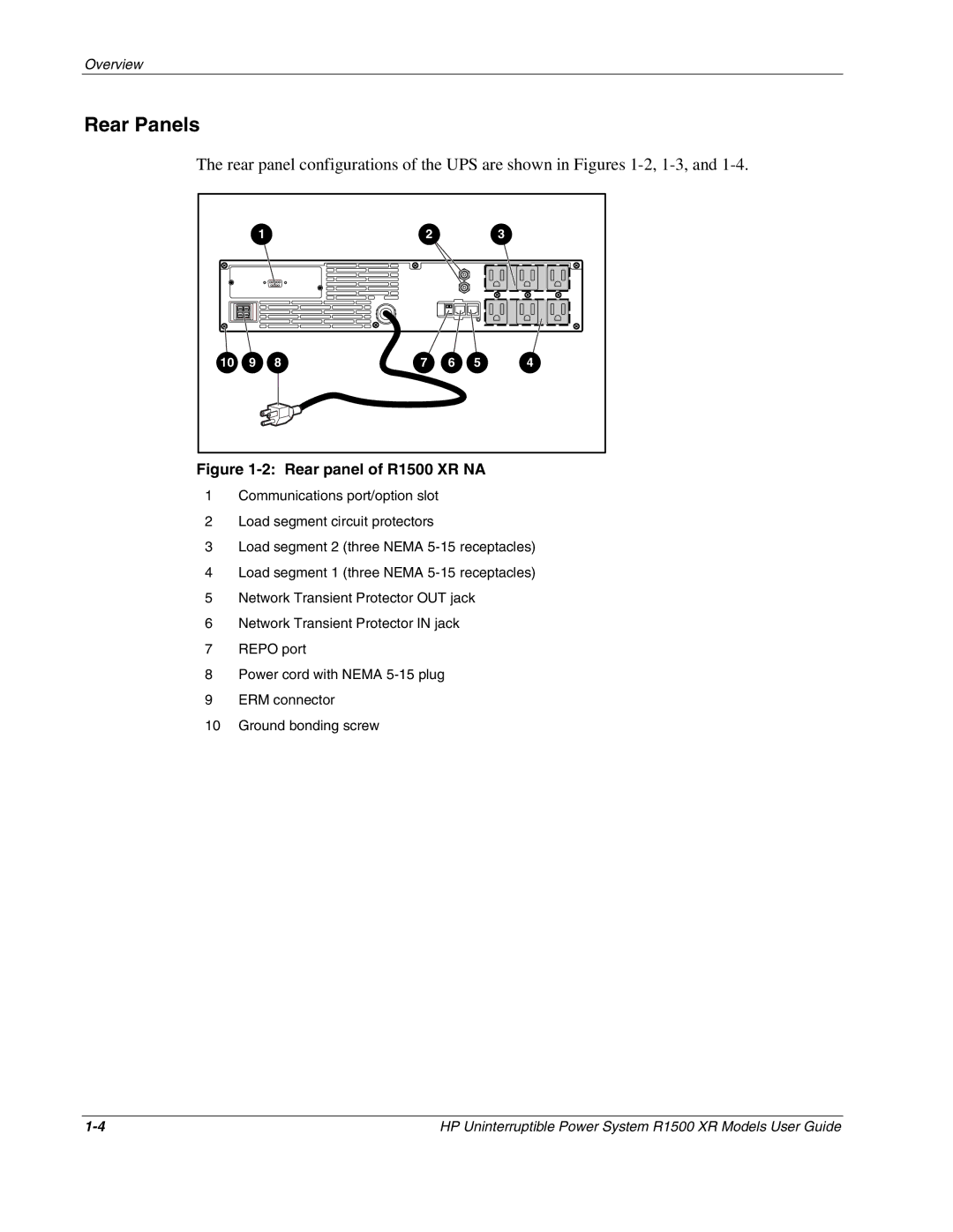
The rear panel configurations of the UPS are shown in Figures
1 | 2 | 3 |
10 | 9 | 8 |
7 | 6 | 5 | 4 |
Figure 1-2: Rear panel of R1500 XR NA
1Communications port/option slot
2Load segment circuit protectors
3Load segment 2 (three NEMA
4Load segment 1 (three NEMA
5Network Transient Protector OUT jack
6Network Transient Protector IN jack
7REPO port
8Power cord with NEMA
9ERM connector
10Ground bonding screw
HP Uninterruptible Power System R1500 XR Models User Guide |