Overview
1 | 2 |
3 | 4 |
10 | 9 | 8 | 7 | 6 | 5 |
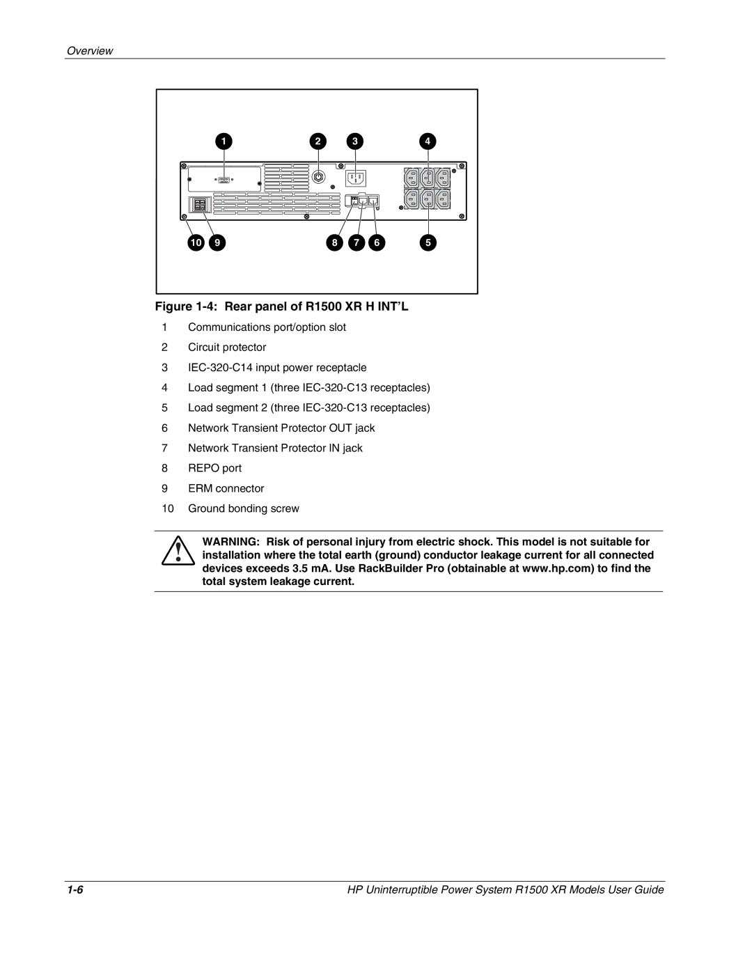
Figure 1-4: Rear panel of R1500 XR H INT’L
1Communications port/option slot
2Circuit protector
3
4Load segment 1 (three
5Load segment 2 (three
6Network Transient Protector OUT jack
7Network Transient Protector IN jack
8REPO port
9ERM connector
10Ground bonding screw
WARNING: Risk of personal injury from electric shock. This model is not suitable for installation where the total earth (ground) conductor leakage current for all connected devices exceeds 3.5 mA. Use RackBuilder Pro (obtainable at www.hp.com) to find the total system leakage current.
HP Uninterruptible Power System R1500 XR Models User Guide |
