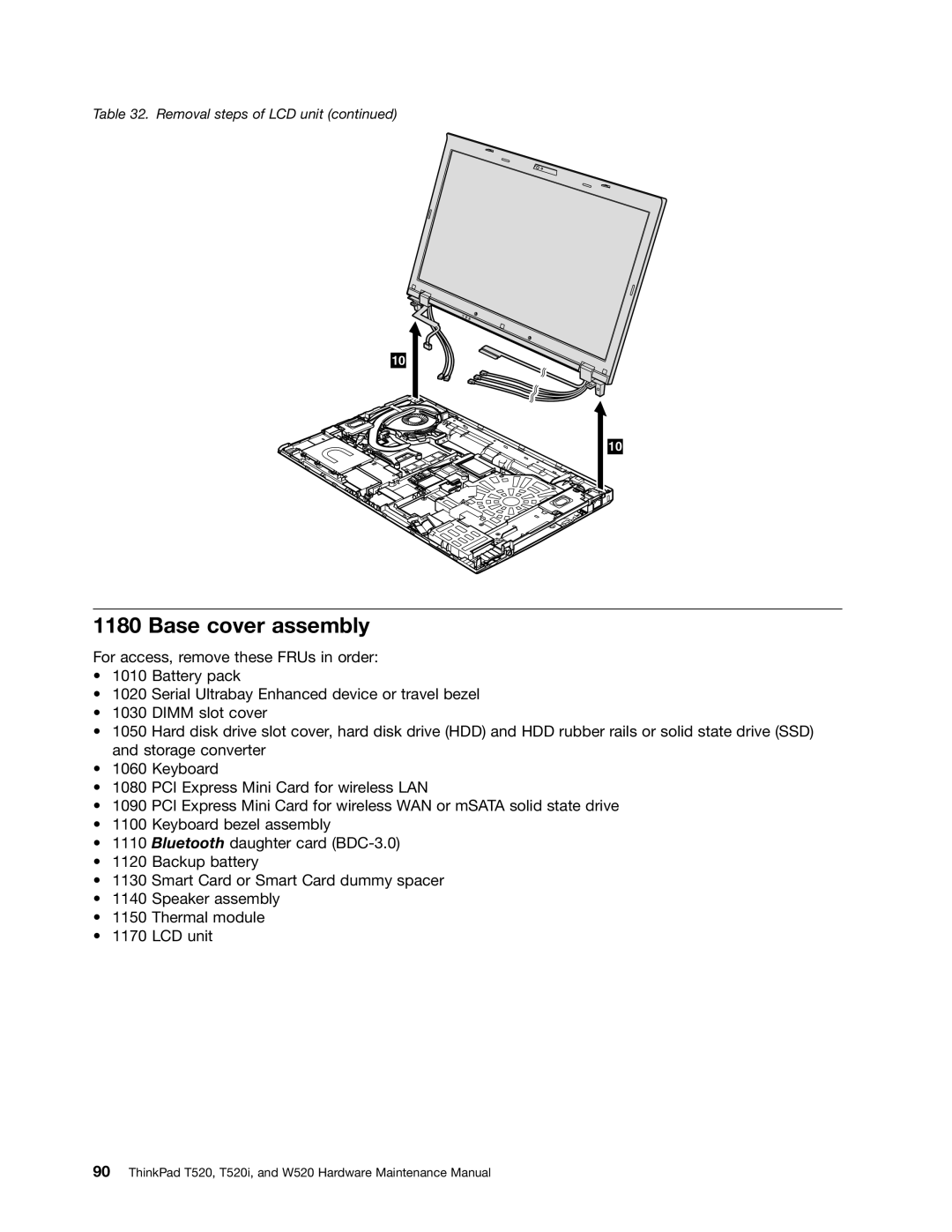
Table 32. Removal steps of LCD unit (continued)
10
10
1180 Base cover assembly
For access, remove these FRUs in order:
•1010 Battery pack
•1020 Serial Ultrabay Enhanced device or travel bezel
•1030 DIMM slot cover
•1050 Hard disk drive slot cover, hard disk drive (HDD) and HDD rubber rails or solid state drive (SSD) and storage converter
•1060 Keyboard
•1080 PCI Express Mini Card for wireless LAN
•1090 PCI Express Mini Card for wireless WAN or mSATA solid state drive
•1100 Keyboard bezel assembly
•1110 Bluetooth daughter card
•1120 Backup battery
•1130 Smart Card or Smart Card dummy spacer
•1140 Speaker assembly
•1150 Thermal module
•1170 LCD unit