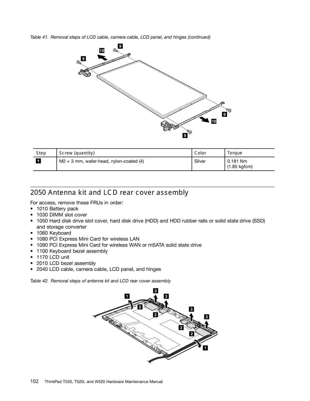
Table 41. Removal steps of LCD cable, camera cable, LCD panel, and hinges (continued)
9
10
9
9
10
9
| Step | Screw (quantity) | Color | Torque | |
|
|
|
|
|
|
|
|
| M2 × 3 mm, | Silver | 0.181 Nm |
| 9 |
| |||
|
|
|
|
| (1.85 kgfcm) |
|
|
|
|
|
|
2050 Antenna kit and LCD rear cover assembly
For access, remove these FRUs in order:
•1010 Battery pack
•1030 DIMM slot cover
•1050 Hard disk drive slot cover, hard disk drive (HDD) and HDD rubber rails or solid state drive (SSD) and storage converter
•1060 Keyboard
•1080 PCI Express Mini Card for wireless LAN
•1090 PCI Express Mini Card for wireless WAN or mSATA solid state drive
•1100 Keyboard bezel assembly
•1170 LCD unit
•2010 LCD bezel assembly
•2040 LCD cable, camera cable, LCD panel, and hinges
Table 42. Removal steps of antenna kit and LCD rear cover assembly
| 3 |
1 | 3 |
2 |
| 3 |
|
| |
| 2 | 3 |
|
|
2
2
1