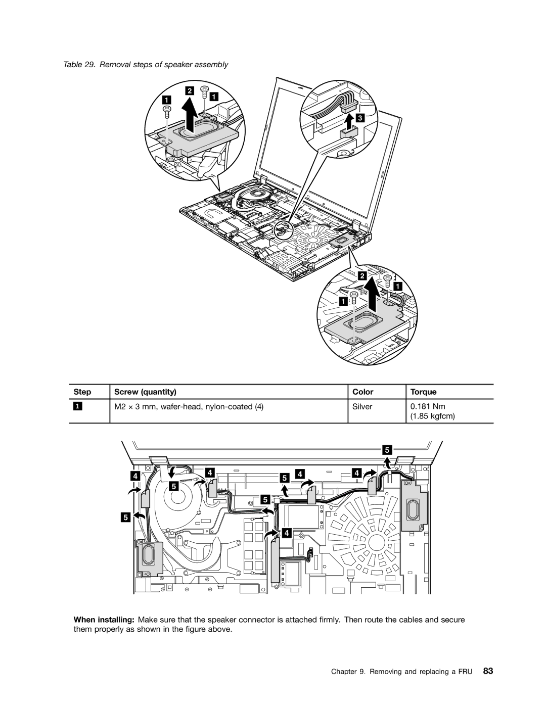
Table 29. Removal steps of speaker assembly
2
11
3
2
1
1
| Step | Screw (quantity) | Color | Torque | |
|
|
|
|
|
|
|
|
| M2 × 3 mm, | Silver | 0.181 Nm |
| 1 |
| |||
|
|
|
|
| (1.85 kgfcm) |
|
|
|
|
|
|
4![]()
![]() 5
5
5 ![]()
4
5
5 | 4 | 4 |
|
|
5
4
When installing: Make sure that the speaker connector is attached firmly. Then route the cables and secure them properly as shown in the figure above.