30 OPERATING INSTRUCTIONS
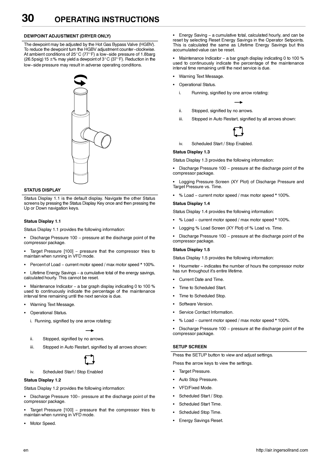
DEWPOINT ADJUSTMENT (DRYER ONLY)
The dewpoint may be adjusted by the Hot Gas Bypass Valve (HGBV). To reduce the dewpoint turn the HGBV adjustment counter−clockwise. At ambient conditions of 25_C (77_F) a low−side pressure of 1.8barg (26.5psig) 15 ±% may yield a dewpoint of 3_C (37_F). Reduction in the
low−side pressure may result in adverse operating conditions.
STATUS DISPLAY
Status Display 1.1 is the default display. Navigate the other Status screens by pressing the Status Display Key once and then pressing the Up or Down navigation keys.
Status Display 1.1
Status Display 1.1 provides the following information:
SDischarge Pressure 100 − pressure at the discharge point of the compressor package.
STarget Pressure [100] − pressure that the compressor tries to maintain when running in VFD mode.
SPercent of Load − current motor speed / max motor speed * 100%.
SLifetime Energy Savings − a cumulative total of the energy savings, calculated hourly. This cannot be reset.
SMaintenance Indicator − a bar graph display indicating 0 to 100 % used to continuously indicate the percentage of the maintenance interval time remaining until the next service is due.
SWarning Text Message.
SOperational Status.
i.Running, signified by one arrow rotating:
ii.Stopped, signified by no arrows.
iii.Stopped in Auto Restart, signified by all arrows shown:
iv.Scheduled Start / Stop Enabled
Status Display 1.2
Status Display 1.2 provides the following information:
SDischarge Pressure 100− pressure at the discharge point of the compressor package.
STarget Pressure [100] − pressure that the compressor tries to maintain when running in VFD mode.
SMotor Speed.
SEnergy Saving − a cumulative total, calculated hourly, and can be reset by selecting Reset Energy Savings in the Operator Setpoints. This is calculated the same as Lifetime Energy Savings but this accumulated value can be reset.
SMaintenance Indicator − a bar graph display indicating 0 to 100 % used to continuously indicate the percentage of the maintenance interval time remaining until the next service is due.
SWarning Text Message.
SOperational Status.
i.Running, signified by one arrow rotating:
ii.Stopped, signified by no arrows.
iii.Stopped in Auto Restart, signified by all arrows shown:
iv.Scheduled Start / Stop Enabled.
Status Display 1.3
Status Display 1.3 provides the following information:
SDischarge Pressure 100 − pressure at the discharge point of the compressor package.
SLogging Pressure Screen (XY Plot) of Discharge Pressure and Target Pressure vs. Time.
S% Load − current motor speed / max motor speed * 100%.
Status Display 1.4
Status Display 1.4 provides the following information:
S% Load − current motor speed / max motor speed * 100%.
SLogging % Load Screen (XY Plot) of % Load vs. Time.
SDischarge Pressure 100 − pressure at the discharge point of the compressor package.
Status Display 1.5
Status Display 1.5 provides the following information:
SHourmeter − indicates the number of hours the compressor motor has run throughout it’s entire lifetime.
SCurrent Date and Time.
STime to Scheduled Start.
STime to Scheduled Stop.
SSoftware Version.
SService Contact Information.
S% Load − current motor speed / max motor speed * 100%.
SDischarge Pressure 100 − pressure at the discharge point of the compressor package.
SETUP SCREEN
Press the SETUP button to view and adjust settings. Press the arrow keys to view the settings.
STarget Pressure.
SAuto Stop Pressure.
SVFD/Fixed Mode.
SScheduled Start / Stop.
SScheduled Start Time.
SScheduled Stop Time.
SEnergy Savings Reset.
en | http://air.ingersollrand.com |
