DTR-8.4
Avis
Important Safety Instructions
Power
Precautions
FCC Information for User
Table of Contents
Table of Contents
Amp
Features
Audio/Video
FM/AM Tuner
Make sure you have the following accessories
Supplied Accessories
Power cord
Speaker cable labels 75/300-ohm antenna adapter
Installing the Batteries
Before Using the DTR-8.4
Using the Remote Controller
Front Panel
Front & Rear Panels
Front & Rear Panels
Display
This connector is for connecting an FM antenna
These push terminals are for connecting an AM antenna
Rear Panel
Digital in Coax 1-3, OPT 1-4 28, 30, 32, 34
DVD
Zone 2 OUT
Video 1 & 2 IN/OUT 29
Video 3 & 4
Amp Mode
Remote Controller
Net-Tune Mode
Remote Controller
DVD Mode
Angle button
Menu button
Last Memory button
Search button
Previous/Next Buttons
CD Mode
RH N Muting button
FR/FF Buttons
MiniDisc Mode
Rec button
Rewind/FF / buttons
Tape Mode
Reverse Play button
Enjoying Home Theater
About Home Theater
Speaker Configuration
Positioning Your Speakers
Connecting the DTR-8.4
Attaching the Speaker Labels
Connecting Your Speakers
Connecting the DTR-8.4
Connecting the Speaker Cables
Connecting a Powered Subwoofer
Connecting the AM Loop Antenna
Connecting Antenna
Connecting the Indoor FM Antenna
Attach the FM antenna, as shown A. and Canadian Models
Connecting an Outdoor AM Antenna
Connecting an Outdoor FM Antenna
AV Cables & Sockets
Before Making Any Connections
Optical Digital Inputs
RCA/phono AV Connection Color Coding
Using Composite Video
Connecting Your TV or Projector
Using S-Video
Using Component Video
Using Coaxial or Optical Connections
Connecting a DVD Player
Using Analog Connections
Video Connections
Using Multichannel Connections
Connecting a VCR for Playback
You can play a video from a VCR via the DTR-8.4
Connecting a D-VHS VCR for Playback
Playback from the Recording VCR
Connecting a VCR for Recording
TV, Satellite, cable, set-top box, LD player, etc
PRSatellite, cable, set-top box, LD player, etc
Camcorder Games console, etc
Connecting a Camcorder, Games Console, etc
Camcorder
Connecting a Cassette Recorder
Connecting a CD Player
Connecting a DAT, CD, or MD Recorder
Using Optical or Coaxial Connections
Using Coaxial or Optical Connections playback only
Connecting a Turntable
Digital Recording
Digital source DAT, CD, MD player
Connecting Components
Connecting a Power Amp
With Remote Interactive you can control your
Following special functions
Connecting the RS232 Port
Connecting the Power Cords of Other Components
Connecting the Power Cord
Standby indicator lights up
Turning On the DTR-8.4
Turning On the DTR-8.4 with the Remote Controller
Press the Standby/On button to turn on the DTR-8.4
Press the scroll wheel
THX
Speaker Settings
Basic Setup
Speaker Impedance
Speaker Config menu appear
Speaker Setup menu appears
Crossover Frequency
Speaker Distance
Setup menu closes
Use the Up/Down / but
Then press the Enter but- ton
Speaker Level Calibration
Digital Setup
Input Setup
Tons to select 2. Input Setup
Roll the scroll wheel to select
Video Setup menu appears
Video Setup
Name of the currently selected
DVD in this case
Video Setup menu appears
Component Video Setup
Ton
INPUT1 Select if the video compo- nent is connected to COM
Changing the DTR-8.4’s Remote Control ID
Remote Setup
Setup, and then press the Enter button
Specifying the Location of an IR Receiver
Specifying the TV System Australian model only
Changing the Remote Controller’s Control ID
DTR-8.4En.book Page 50 Thursday, October 16, 2003 1109 AM
Selecting the Source AV Component
Basic Operation
Start playback on the selected AV component
Using the Sleep Timer remote controller only
Muting the DTR-8.4 remote controller only
Setting the Display Brightness
Using Headphones
Fixing the Digital Input Format
Setting the Input Signal Format
Input source you want to set
Press the Audio SEL button
Tuning into Radio Stations
Using the Tuner
Presetting Radio Stations
To select the presets
Selecting Presets Deleting Presets
Ory button, press the FM Mode
Press the Tuner input selector
About the Listening Modes
Listening Modes
DSP Modes
DTS
Selecting Listening Modes
Dolby Digital/Dolby Digital EX
Using the Digital Surround Modes
DTS/DTS-ES Discrete/DTS-ES Matrix
THX Surround EX Dolby Digital
Displaying Source Information
Display Indicators & Source Info
Using the Re-EQ function
Adjusting the Volume of Individual Speakers
Using the Late Night function Dolby Digital only
Setting the Multichannel Input
Using the Multichannel Input
Advanced Operation
Main menu appears
Selecting the Multichannel Input
Advanced Operation
Recording a Separate Input Source
Recording
Recording the Current Input Source
Recording Separate AV Sources
Advanced Setup
Audio Adjust Functions
Advanced Setup
Tons to select 3. Audio Adjust
Assigning the a & B 12V Trigger Outputs
Tone Control
Delay
Surround Speakers
Sound Effect
LFE Level
Theater-Dimensional
Mono
THX
Surround
Volume Setup
Setting Preferences
Headphones Level
OSD Setup
Naming Presets & Input Sources
OSD Position
IntelliVolume menu appears
Using IntelliVolume
Repeat until you’ve
Entered all 10 characters
About Net-Tune
Net-Tune
Internet Radio
Net-Tune
Networking Your DTR-8.4
Net-Tune
Press the Enter button
Using Internet Radio
Tons to select Genres, Location
Or Language
Selecting Internet Radio Presets
Presetting Internet Radio Stations
Deleting Internet Radio Presets
Playing network audio server Tracks
Playing Net-Tune Tracks Randomly
Selecting Items by Letter
Playing Net-Tune Tracks Repeatedly
Music Server Settings
Press the scroll wheel, and then Press the Setup button
2Network Settings
Network Setup menu appears
IP Address menu is shown here
Client Setup
Proxy Setup
IP Address
Mac Address
Using a Receiver/Integrated Amp in Zone
Connecting Zone
Using Only Speakers in Zone
Using a Power Amp in Zone
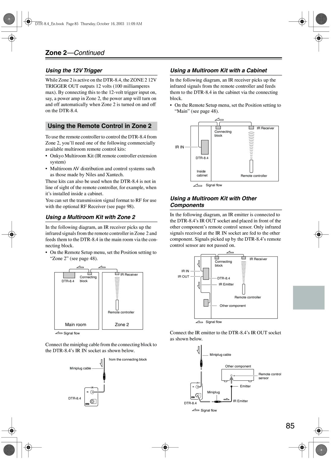
Using the 12V Trigger
Using the Remote Control in Zone
Using a Multiroom Kit with a Cabinet
Using a Multiroom Kit with Zone
Tons to select 2. Surr Back
Setting the Surr Back/Zone 2 Outputs
Zone2, and then press
Surr Back/ Zone2 menu appears
Controlling Zone
Entering a Remote Control Code
Using the Remote Controller with Other Components
Remote Control Codes for an Integra/ Onkyo DVD Player
Remote Control Codes
Using the Remote Controller with Other Components
DTR-8.4En.book Page 90 Thursday, October 16, 2003 1109 AM
Following buttons control the DTR-8.4
Controlling a Satellite Receiver Controlling a VCR
Controlling a Cable Receiver
Controlling a TV
Learning Commands from Another Remote Controller
Making Macros
Using Macros
Naming Macros
Running Macros
Adding New Remote Controller Modes
Editing Remote Controller Modes
Reordering the Remote Controller Modes
MODE, and then press
Assigning Remote Controller Modes
Deleting Remote Controller Modes
Resetting the Remote Controller
Troubleshooting
Troubleshooting
Surr Back speaker setting doesn’t appear?
Can’t learn commands from other remote con- trollers?
Can’t access Internet radio or the network audio server?
Can’t control other components?
Can’t change a setting?
Sound changes when I connect my head- phones?
Can’t use an audio adjust function?
Hardware Setup does not appear in the menu?
Amplifier Section
Specifications
General
Video Section
104
Enjoying Home Theater
DTR-8.4
Connecting the Speaker Cables
Connecting Your Speakers
Connecting a TV
Connecting Your TV & DVD Player
Using Composite Video or S-Video
Turning On the DTR-8.4
Playing a DVD
Adjust the volume
Selecting Listening Modes
Select the DVD input source
Networking the DTR-8.4/7.4
DTR-8.4/7.4 Net-Tune Quick Start Guide