Chapter 5 Installation
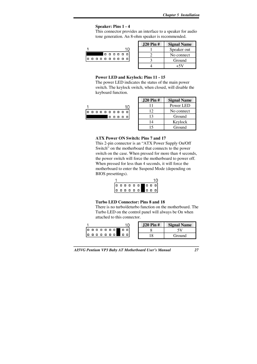
Speaker: Pins 1 - 4
This connector provides an interface to a speaker for audio tone generation. An
| J20 Pin # |
|
| Signal Name |
|
| 1 |
|
| Speaker out |
|
| 2 |
|
| No connect |
|
| 3 |
|
| Ground |
|
| 4 |
|
| +5V |
|
Power LED and Keylock: Pins 11 - 15
The power LED indicates the status of the main power switch. The keylock switch, when closed, will disable the keyboard function.
| J20 Pin # |
|
| Signal Name |
|
| 11 |
|
| Power LED |
|
| 12 |
|
| No connect |
|
| 13 |
|
| Ground |
|
| 14 |
|
| Keylock |
|
| 15 |
|
| Ground |
|
ATX Power ON Switch: Pins 7 and 17
This
Turbo LED Connector: Pins 8 and 18
There is no turbo/deturbo function on the motherboard. The Turbo LED on the control panel will always be On when attached to this connector.
|
| J20 Pin # |
|
| Signal Name |
|
| |
| 8 |
|
|
| 5V |
| ||
| 18 |
|
|
| Ground |
| ||
|
|
|
|
|
|
|
|
|
AI5VG Pentium VP3 Baby AT Motherboard User’s Manual | 27 | |||||||