Intel Celeron M Processor Subcompact Board With LVDS, Ethernet
GENE-8310
6 Channel Audio & Mini PCI
SubCompact Board
Copyright Notice
Acknowledgments
Packing List
Chapter 1 General Information
Contents
Chapter 2 Quick Installation Guide
Appendix A Programming The Watchdog Timer
Chapter 3 Award BIOS Setup
Chapter 4 Driver Installation
I/O Information
Appendix B
IRQ Mapping Chart
I/O Address Map
Chapter 1 General Information 1
General Information
Chapter
1.1 Introduction
Superb Performance and Controllable Power Usage
Multiple Display Modes
Chapter 1 General Information
Wide Expansion Capability
48-bit Dual Channels LVDS TFT LCD 10/100Mbps Fast Ethernet
1.2 Features
AC-97 3D Surround 5.1 Channel Audio
Supports Type II CompactFlash Memory
System
1.3 Specifications
Display
support Wake-up function
Two 5 x 2 Pin Headers Support
4 USB 2.0 Ports Does not
Part No. 2007831011 Printed in Taiwan JAN
Quick Installation Guide
Chapter 2 Quick Installation Guide
2.1 Safety Precautions
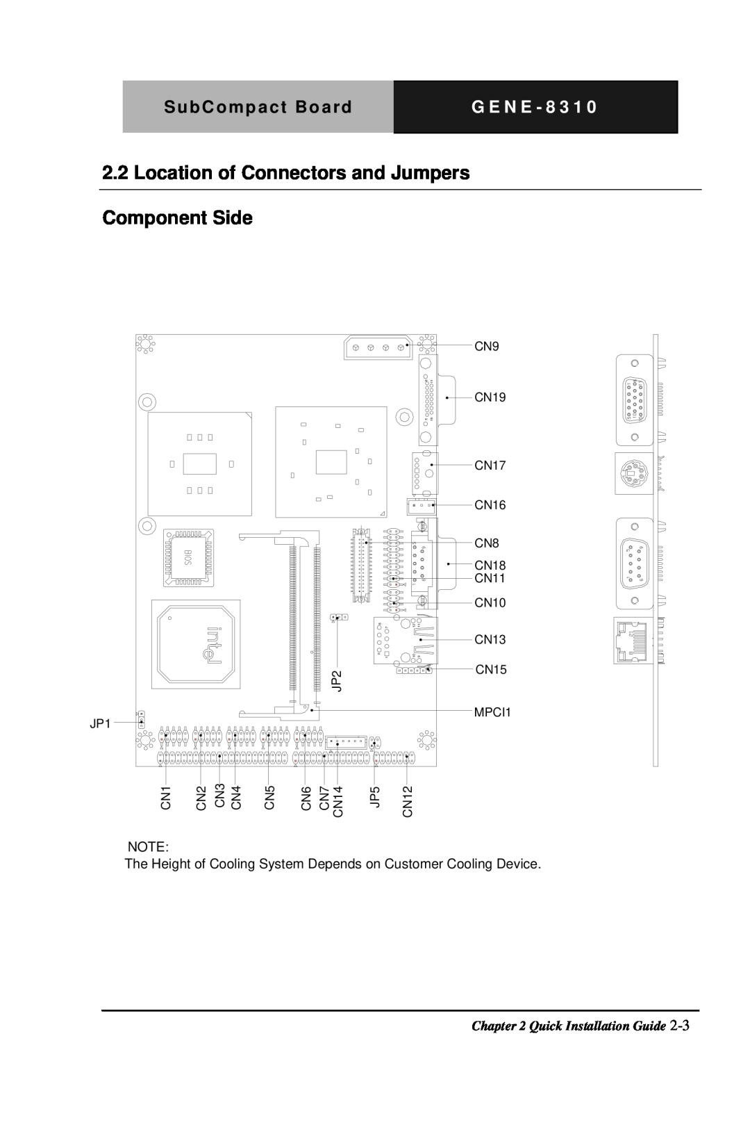
The Height of Cooling System Depends on Customer Cooling Device
2.2 Location of Connectors and Jumpers Component Side
CFD1 DIMM1
Solder Side
Component Side
2.3 Mechanical Drawing
The Height of Cooling System Depends on Customer Cooling Device
103.51
133.93
3.23 8.89 0.00 72.39 0.58 114.30
0.58
0.00
2.4 List of Jumpers
Jumpers
Label
Function
2.5 List of Connectors
Connectors
CN17
Closed
2.6 Setting Jumpers
Open
2.7 Clear CMOS Selection JP1
2.10 USB2.0 Port 1 Connector CN1
2.8 LCD Voltage Selection JP2
2.9 COM2 RI/+5V Selection JP5
2.12 Primary IDE Hard Drive Connector CN3
2.11 USB2.0 Port 2 Connector CN2
Name
2.13 Digital IO Connector CN4
DIO Address is 801H
2.14 Front Panel CN5
2.15 Serial Port COM2 Connector CN6
2.16 Parallel Port Connector CN7
PinSignal
2.17 Dual Channel LVDS Connector CN8
2.18 4P Power Connector CN9
2.21 Audio Input/Output Connector CN12
2.19 TV-Out Connector CN10
2.20 DVI Connector CN11
2.23 External 5VSB/PWRGD Connector CN14
2.22 Ethernet 10/100Base-TX RJ-45 Phone Jack Connector CN13
2.24 IrDA Connector CN15
G E N E - 8
2.27 Serial Port COM1 Connector CN18
2.25 Fan Connector CN16
2.26 Mini-DIN PS/2 Connector CN17
2.29 External Battery VBAT2
2.28 CRT Display Connector CN19
2.30 Mini PCI Slot MPCI1
2.31 CompactFlash Disk Slot CFD1
G E N E - 8 3 1
Chapter 3 Award BIOS Setup
Award BIOS Setup
3.1 System Test and Initialization
System configuration verification
Standard CMOS Features
Entering Setup
Advanced BIOS Features
Advanced Chipset Features
PnP/PCI Configurations
Power Management Setup
Load Fail-Safe Defaults
Load Optimized Defaults
Exit Without Saving
Set Supervisor/User Password
Save and Exit Setup
Chapter 4 Driver Installation
Driver Installation
Follow the sequence below to install the drivers
Chapter4 Drivers Installation
4.1 Installation
Step 4 - Install Realtek AC97 codec Driver
Appendix A Programming the Watchdog Timer A-1
Programming the Watchdog Timer
Appendix
Appendix A Programming the Watchdog Timer A-2
Configuring Sequence Description
A.1 Programming
3 Exit the MB PnP Mode
1 Enter the MB PnP Mode
2 Modify the Data of the Registers
Appendix A Programming the Watchdog Timer A-4
Configure Control Index=02h
WatchDog Timer Configuration Registers
WatchDog Timer Configuration Register Index=72h, Default=00h
WatchDog Timer Control Register Index=71h, Default=00h
WatchDog Timer Time-out Value Register Index=73h, Default=00h
Appendix A Programming the Watchdog Timer A-5
A.2 ITE8712 Watchdog Timer Initial Program
game port enable mov cl call SetLogicDevice InitialOK
CALL ReadConfigurationData CMP AL,87h JNE NotInitial MOV AL,21h
RET ExitConfigurationMode ENDP CheckChip PROC NEAR MOV AL,20h
CALL ReadConfigurationData CMP AL,12h JNE NotInitial NeedInitial STC
RET NotInitial CLC RET CheckChip ENDP ReadConfigurationData PROC NEAR
MOV DX,WORD PTR CSCfgPort+06h IN AL,DX RET ReadConfigurationData ENDP
Appendix A Programming the Watchdog Timer A-10
END Main
SetLogicDevice proc near push ax push cx xchg al,cl mov cl,07h
call SuperioSetReg pop cx pop ax ret SetLogicDevice endp
Appendix B I/O Information B-1
I/O Information
Appendix B I/O Information B-2
B.1 I/O Address Map
B.2 1st MB Memory Address Map
Appendix B I/O Informaion B-3
B.3 IRQ Mapping Chart
B.4 DMA Channel Assignments