Manuals
/
Intelligent Motion Systems
/
Household Appliance
/
Home Safety Product
Intelligent Motion Systems
MDrive34AC
manual
Appendix C, Optional Cables and Cordsets
Models:
MDrive34AC
1
70
81
81
Download
81 pages
35.76 Kb
67
68
69
70
71
72
73
74
Specs
SPI Signal Overview
Fault Output
Pin Assignment and Wire Colors
Warranty
Dimension
Configuring
Options and Accessories
Setup Parameters
SPI Commands and Parameters
Page 70
Image 70
Page 69
Page 71
Page 70
Image 70
Page 69
Page 71
Contents
42TM
Excellence in MotionTM
34 TM
OPERATING INSTRUCTIONS
inaccuracies
Low Voltage Installation Information
MDriveAC Plus Microstepping Revision R031808
Qualification of personnel
Important information
Intended Use
This page intentionally left blank
Part 2 Interfacing and Configuration
Table Of Contents
Part 1 Hardware Specifications
1-13
2-12
Section 2.3: Using the IMS SPI Motor Interface
Section 2.4: Using User-DefinedSPI
2-21
Part 2: Interfacing and Configuration
List Of Figures
Part 1: Hardware Specifications
Appendices
Part 2: Interfacing and Configuration
List of Tables
Part 1: Hardware Specifications
Appendices
GETTING STARTED
Connecting AC Power
Connect Opto Power and Logic Inputs
MDriveAC Plus Microstepping
Motion Settings DialogInput Settings Dialog
Connecting Parameter Setup Cable
Install the IMS SPI Motor Interface
Figure GS.2: MDriveAC Plus CD
Excellence in Motion TM
PART HARDWARE SPECIFICATIONS
mICROSTEPPING
Page Intentionally Left Blank
Relevant to Firmware Version
SECTION
Configuring
Features and Benefits
Introduction to the MDrive34AC Plus Microstepping
20 Microstep Resolutions up to
Thermal Specifications
General Specifications
Electrical Specifications
I/O Specifications
Motor Specifications
Setup Parameters
MDriveAC Plus Microstepping Setup Parameters
Default
Connectors
Mechanical Specifications
Dimensions in Inches mm
Control Knob
NEED A CABLE?
Pin Assignment and Description
available to interface to the 19-PinM23 Connector
The following cordset is
Pin #
Pin Assignment - P1 I/O, SPI and Encoder
Connections
Function
Inside: Pins 13 -
Outside: Pins 1
Options and Accessories
Features and Benefits
Introduction to the MDrive42AC Plus Microstepping
Configuring
Motor, Power Supply, and Drive Electronics
20 Microstep Resolutions up to
I/O Specifications
Electrical Specifications
Thermal Specifications
Communications Specifications
Default
Setup Parameters
MDriveAC Plus Microstepping Setup Parameters
Table 1.4.1: Setup Parameters
Connectors
Mechanical Specifications
Dimensions in Inches mm
P1 P3
NEED A CABLE?
available to interface to the 19-PinM23 Connector
Pin Assignment and Description
The following cordset is
Pin #
Pin Assignment - P1 I/O, SPI and Encoder
Connections
Function
Inside: Pins 13 -
Outside: Pins 1
Pin Pin Pin
Internal Encoder
Options and Accessories
Parameter Setup Cable and Adapter
Control Knob
Section 2.3: Using the IMS SPI Motor Interface
PART INTERFACING AND CONFIGURING
Section 2.2: Connecting SPI Communications
Section 2.4 Using User-DefinedSPI
Page Intentionally Left Blank
Relevant to Firmware Version
Optically Isolated Logic Inputs
Isolated Logic Input Pins and Connections
Logic Interface and Connection
MD-CS10x-000Wire Color Reference
Direction
Isolated Logic Input Characteristics
Step Clock
Quadrature
UP/DOWN CW/CCW TIMING
STEP/DIRECTION TIMING
QUADRATURE TIMING
Figure 2.1.3: Clock Input Timing Characteristics
Microstepping
Optocoupler Reference
MDriveACPlus
Optocoupler Reference
PNP Open Collector Interface Sourcing
NPN Open Collector Interface Sinking
MDriveACPlus Microstepping
Input Connection Examples
Fault Temperature Warning Output
Switch Interface Sinking
Switch Interface Sourcing
Switch Interface Example
Figure 2.1.7: Fault Output interfaced to an LED
Minimum Required Connections
Figure 2.1.8 Minimum Required Connections
SPI Signal Overview
Connecting SPI Communications
Connecting the SPI Interface
+5 VDC Output
Microstepping #2
SPI Pins and Connections
MDriveACPlus Microstepping #1 MDriveACPlus
2-11
Color Coded Parameter Values
Using the IMS SPI Motor Interface Installation
Configuration Parameters and Ranges
MDriveAC Plus Microstepping Setup Parameters
File
View Settings Screen
IMS SPI Motor Interface Menu Options
Perform File Operation
Help
Upgrade
Recall
2-14
1.MSEL: Microstep Resolution Select
MSEL Microstep Resolution Selection
Exit
Connected/Disconnected Indicator
Factory
HCDT Hold Current Delay Time
Enable Active High/Low
Screen 2 I/O Settings Configuration Screen
Input Clock Filter Settings
Input Clock Type
IMS Part Number/Serial Number Screen
Fault Indication
MDriveAC Plus Microstepping Fault Codes
Upgrade Instructions
The IMS SPI Upgrader Screen
2.Serial Number: the serial number of your unit
Communications Port Operations
Initialization Screen
Port Menu
Check Sum Calculation for SPI
Using User-DefinedSPI
SPI Timing Notes
SECTION
Table 2.4.1: SPI Commands and Parameters
SPI Commands and Parameters
2-22
Relevant to Firmware Version
Write
READ
SPI Communications Sequence
Page Intentionally Left Blank
Relevant to Firmware Version
Appendix C: Optional Cables and Cordsets
APPENDICES
Appendix B: Gear Boxes
Appendix D: Interfacing an Encoder
Page
MDrive34AC Plus Microstepping
Motor Specifications
MDriveAC Plus Microstepping Motor Performance
MDrive34AC – 120VAC
MDrive42AC Plus Microstepping
Double Length
Triple Length
MDrive42AC – 120VAC
Double Length
Motor Specifications
Single Length
1147 oz-in/810 N-cm
Section Overview
APPENDIX B
MDrive with Planetary Gearbox
Product Overview
Calculating the Shock Load Output Torque TAB
Example
Figure B.1: MDrive23 Torque-SpeedCurve
Table B.1: Planetary Gearbox Operating Factor
Weight of
Conveyor Belt
A-11
A-12
A-13
MDrive34AC Plus2 Planetary Gearbox Parameters
Planetary Gearbox for MDrive34AC Plus2
A-14
PM81 Gearbox Ratios and Part Numbers
A-15
Planetary Gearbox for MDrive42AC Plus2
PM105 Gearbox Ratios and Part Numbers
A-16
PM120 Gearbox Ratios and Part Numbers
APPENDIX C
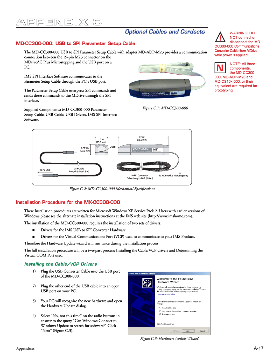
MD-CC300-000 USB to SPI Parameter Setup Cable
Installation Procedure for the MX-CC300-000
Optional Cables and Cordsets
A-18
A-19
Determining the Virtual COM Port VCP
Adapter
A-20
P1 - Expanded I/O Configuration
MD-CS10x-000Cordset
Pin Assignment and Wire Colors
Function
3-PinEuro AC Connector
MD-CS20x-000Cordset
Table C.2: Euro AC Wire Color Chart
MD-CS200-000
MDriveAC Plus Microstepping
Pin Configuration
APPENDIX D
Factory Mounted Encoder
Encoder Signals
A-24
Linear Slide Option
Features
APPENDIX E
MDrive34Plus Linear Slide
Mechanical Specifications
A-26
Specifications
Screw
OBTAINING WARRANTY SERVICE
TWENTY-FOUR24 MONTH LIMITED WARRANTY
WARRANTY
intelligent motion systems, INC
Excellence in Motion
Top
Page
Image
Contents