Everyday and Sport Series Wheelchairs
Owner’s Operator and Maintenance Manual
Top End Everyday Series
Top End Sports Series
Everyday and Sport Series Wheelchairs
TABLE OF CONTENTS
TABLE OF CONTENTS
SECTION 3-SAFETY INSPECTION
REGISTER YOUR PRODUCT
SECTION 6-SEAT
SECTION 5-WHEELS
TABLE OF CONTENTS
TABLE OF CONTENTS
SECTION 7-FOOTREST
LIMITED WARRANTY
ANTI-TIPPER
All Wheelchairs with Swivel Anti-tip Except
or Complete and mail the form on the next page
REGISTER YOUR PRODUCT
City State/Province
Cut Along Line
Fold
here
Invacare Product Registration Form Please Seal with
Fold here Cut Along Line Fold here
Tape Before Mailing
Everyday and Sport Series Wheelchairs
WHEELCHAIR TIE-DOWN RESTRAINTS AND SEAT POSITIONING STRAPS
SPECIAL NOTES
TYPICAL PRODUCT PARAMETERS
NOTE All specifications are approximate
TYPICAL PRODUCT PARAMETERS
TERMINATOR
NOTE All specifications are approximate
TERMINATOR TITANIUM
TYPICAL PRODUCT PARAMETERS
EVERYDAY ED
AND QUAD RUGBY
TITANIUM
NOTE All specifications are approximate
TYPICAL PRODUCT PARAMETERS
TYPICAL PRODUCT PARAMETERS
NOTE All specifications are approximate
PAUL SCHULTE SIGNATURE BB
T-5 TENNIS ELITE
TRANSFORMER ALL-SPORT
NOTE All specifications are approximate
TYPICAL PRODUCT PARAMETERS
Operating Information
SECTION 1-GENERAL GUIDELINES
Stability Warning
DO NOT tip the wheelchair without assistance
Tire Pressure and Information
Weight Training
Weight Limitation
Stability and Balance
SECTION 2-SAFE HANDLING
A Note to Wheelchair Assistants
Percentage of Weight Distribution
Coping with Everyday Obstacles
Rear of Center ofWheelchair Gravity
Reaching, Leaning and Bending - Forward
Reaching, Leaning - Backwards
DO NOT tip the wheelchair without assistance
Tipping
Tipping - Curbs
Stairways
Transferring To and From Other Seats
Inspect Initially
SECTION 3-SAFETY INSPECTION
Safety Inspection Checklist
SECTION 3-SAFETY INSPECTION
Inspect/Adjust Weekly
Inspect/Adjust Monthly
Inspect/Adjust Periodically
Troubleshooting
Suggested Maintenance Procedures
Maintenance
Maintenance Safety Precautions
10. Check upholstery for sagging, rips or tears
Back MUST be locked securely in place before using the wheelchair
Back Angle Adjustment
NOTE For this procedure, refer to FIGURE
SECTION 4-BACK
3. Adjust back canes to back angle required
Installing Foldover Back Upholstery
Removing/Installing Foldover Back Upholstery
Removing Foldover Back Upholstery
NOTE For this procedure, refer to FIGURE
The Adjustable Tension Straps
Adjustable Tension Back Upholstery
Replacing Adjustable Tension Back Upholstery
The Back Upholstery Cover
NOTE Both back canes should be adjusted to the same height
Back Height Adjustment Adjustable Backs Only
NOTE Observe the tautness of the back upholstery for reinstallation
Push pin MUST be protruding through hole in back cane
3. Reinstall the fastening flaps onto the back canes
NOTE The fastening flap with logo is for the left back cane
NOTE Right and left is determined by sitting in the wheelchair
Keep locking pins clean
Removing/Installing Rear Wheels
SECTION 5-WHEELS
NOTE For this procedure, refer to FIGURE
is not visible when inserted into camber bar
Adjusting Quick-Release Axles
Replacing Quad-Release Axles
NOTE End of Quick Release
In and/or Out
Adjusting Quad-Release Handles
Removing Play from Rear Wheels
NOTE For this procedure, refer to FIGURE
NOTE For this procedure, refer to FIGURE
Handrim Replacement
Repairing/Replacing Rear Wheel, Tire/Tube
NOTE For this procedure, refer to FIGURE
Opening/Closing Camber Clamps
SECTION 5-WHEELS
FIGURE 5.6 Opening/Closing Camber Clamps
Camber Clamp Closed Position Quick ReleaseOpen Position Lever
Socket Screw Camber Clamp
Camber Tube
Adjusting Rear Wheel Camber
A4 Camber System
NOTE For this procedure, refer to FIGURE
NOTE For this procedure, refer to FIGURE
Determining Toe In/Toe Out
NOTE For this procedure, refer to FIGURE
Adjusting Toe In/Toe Out
Camber Tube
Front of Wheelchair 12-inches Rear of Wheelchair
NOTE Make the following adjustment for one camber at a time
Course Adjustment
NOTE Rear wheels are removed from the
NOTE For this procedure, refer to FIGURE
SECTION 5-WHEELS
Fine Adjustment
NOTE For this procedure, refer to FIGURE
adjustment
Adjusting Wheelbase Length Adjusting Center of Gravity
how the adjustment rings can be positioned
drawings for clarity, there is no need to remove
Hex Screw
Non-Suspension - Top View
Remove
Lengthening
NOTE The wheelbase width can be increased/decreased by 1‐inch
Adjusting Wheelbase Width
NOTE For this procedure, refer to FIGURE
NOTE For this procedure, refer to FIGURE
Indexing
Replacing Axle Tube
NOTE For this procedure, refer to FIGURE
15. Adjust the axle tube. Refer to Adjusting the Axle Tube on page
NOTE DO NOT close the camber clamps at this time
NOTE Stand behind the wheelchair to determine left or right
Adjusting the Axle Tube
NOTE For this procedure, refer to FIGURE
NOTE For this procedure, refer to FIGURE
Camber Tube
A4 Camber System
11. Repeat STEP
NOTE For this procedure, refer to FIGURE
Replacing/Adjusting Casters
before performing this procedure
Adjusting Front Caster Height
NOTE For this procedure, refer to
NOTE When changing a rear wheel/front
NOTE For this procedure, refer to FIGURE
Wheel Lock Adjustment/Replacement
NOTE Rear wheel not shown for clarity
FIGURE 5.20 Wheel Lock Adjustment/Replacement
NOTE High mount wheel lock shown for clarity
Wheel Lock Adjustment
SECTION 6-SEAT
Replacing Adjustable Tension Seat Upholstery
NOTE For this procedure, refer to FIGURE
NOTE Right and left is determined by sitting in the wheelchair
Replacing Screw-On Seat Upholstery
FIGURE 6.1 Replacing Adjustable Tension Seat Upholstery
FIGURE 6.2 Replacing Screw-On Seat Upholstery
NOTE For this procedure, refer to FIGURE
Adjusting Front Seat Height
Adjusting Transformer Seat Height
Adjusting Rear Seat Height
NOTE The footrest tubing will slide once the hardware is removed
Adjustment Holes
FIGURE 6.3 Adjusting Transformer Seat Height
Coved Washer Adjustment Screw
SECTION 6-SEAT
SECTION 7-FOOTREST ANTI-TIPPER
Adjusting the Footrest
Replacing the Footrest
Adjusting/Replacing Standard Footrest
Replacing/Adjusting Optional A4 Footrest
Installing/Adjusting Optional Clamp on Raised Footrest
Installing
Adjusting
Adjusting Footplate Angle
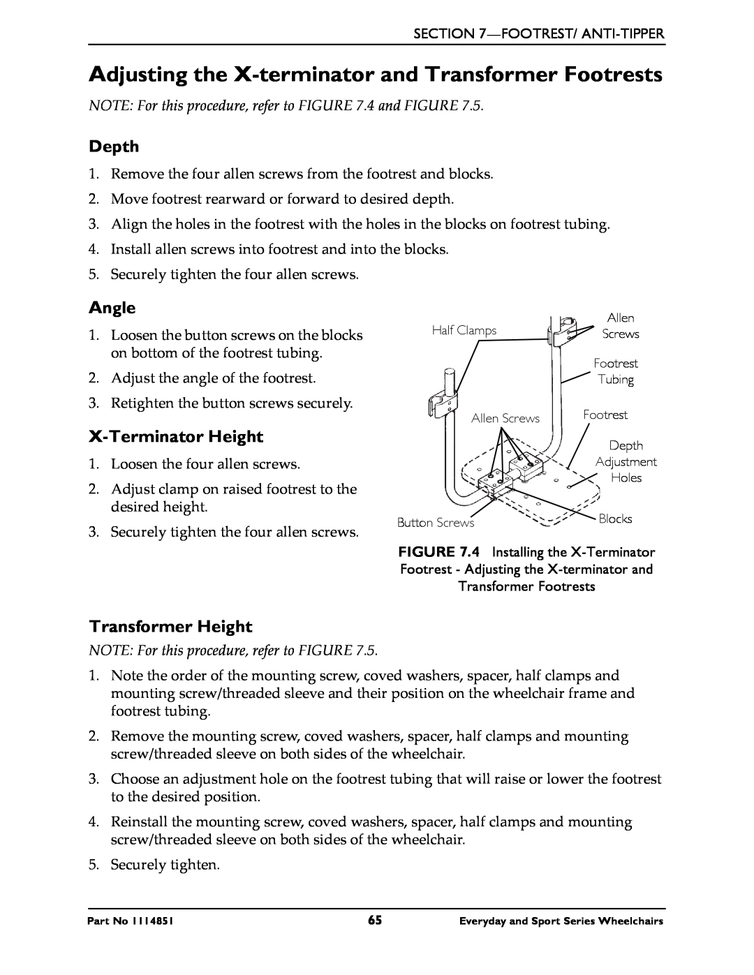
Installing the X-Terminator Footrest
Adjusting Footplate Depth
NOTE Observe the angle of footplate for reinstallation
NOTE For this procedure, refer to FIGURE 7.4 and FIGURE
Adjusting the X-terminator and Transformer Footrests
Depth
Angle
NOTE For this procedure, refer to FIGURE
Adjusting/Replacing Anti-tipper
Ensure both anti-tippers are adjusted to the same height
Replacing Anti-tipper
Adjusting Anti-tipper
Installing/Depth Adjustment
Installing/Removing/Adjusting Swivel Anti-Tip
Removing
NOTE This applies to any Terminator ordered with swivel anti‐tip
NOTE For this procedure, refer to FIGURE 7.2, Detail A
Adjusting Height
Paul Schulte Signature BB and T-5 Tennis Elite Models ONLY
NOTE View
Elastomers and Suspension
SECTION 8-SUSPENSION
Replacing Rear Elastomers
NOTE For this procedure, refer to FIGURE
NOTE For this procedure, refer to FIGURE
Replacing Front Elastomers
NOTE One mounting screw will not turn
SECTION 8-SUSPENSION
FIGURE 8.2 Replacing Front Elastomers
Upper Portion of Fork Mounting Screw Use Loctite
Lower Portion of Fork Elstaomer Mounting Screw Threaded Sleeve
NOTE The following procedures are for Transformer wheelchairs ONLY
Installing/Removing the Wing/Bumper
SECTION 9-WING/BUMPER
Installing
Everyday and Sport Series Wheelchairs
SECTION 9-WING/BUMPER
LIMITED WARRANTY
LIMITED WARRANTY
Canada