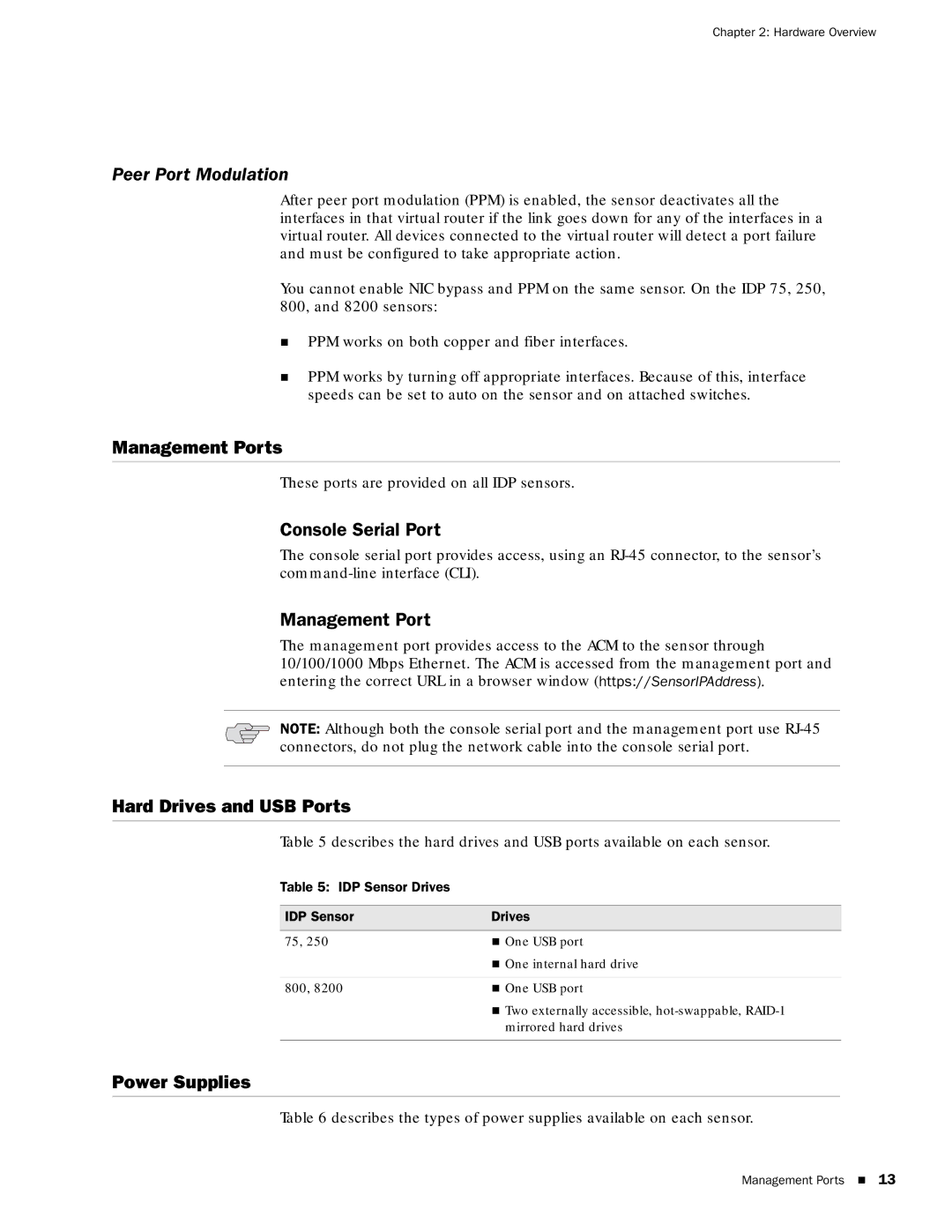
IDP75, IDP 800, IDP8200, IDP250 specifications
Juniper Networks IDP250 is a robust Intrusion Detection and Prevention system designed to provide comprehensive security for enterprise networks. This device plays a crucial role in safeguarding sensitive data and maintaining the integrity of network infrastructures against the ever-evolving landscape of cyber threats.One of the main features of the IDP250 is its advanced threat detection capabilities. The system utilizes deep packet inspection technologies, allowing it to analyze network traffic in real-time. This feature ensures that malicious activities are identified and addressed before they can compromise the network's security. Additionally, the IDP250 is designed to recognize not only known threats but also emerging threats by leveraging heuristic and signature-based detection techniques.
Another significant characteristic of the IDP250 is its ability to integrate seamlessly into existing network infrastructures. It supports a variety of deployment scenarios, whether in-line, out-of-band, or as a dedicated network appliance. This flexibility enables organizations to adapt the IDP250 to their unique needs without extensive reconfiguration of their network topology.
The IDP250 is powered by Juniper’s proprietary software platform, which provides a user-friendly interface for monitoring and managing security incidents. The intuitive dashboard offers insights into network traffic patterns, security alerts, and overall system performance. Organizations can configure custom alerts and reporting features, thereby streamlining incident response and enabling proactive management of potential vulnerabilities.
Scalability is another important aspect of the IDP250. Designed to accommodate growing network demands, the device supports high throughput and can effectively handle large amounts of simultaneous traffic. This scalability ensures that as businesses expand, their security solutions remain robust and effective.
In terms of compatibility, the IDP250 supports various networking protocols and can be integrated with other security solutions, such as firewalls and Security Incident and Event Management (SIEM) systems. This interoperability enables organizations to build a multi-layered security architecture that enhances overall protection.
Finally, the IDP250 comes equipped with comprehensive logging and reporting features. Detailed logs enable security analysts to conduct thorough investigations of security incidents, thus facilitating compliance with industry regulations and standards.
In conclusion, Juniper Networks IDP250 stands out as a powerful and versatile Intrusion Detection and Prevention system. With its advanced threat detection capabilities, seamless integration, scalability, and comprehensive logging features, it is an essential tool for organizations looking to bolster their network security defenses.

