Intrusion Detection and Prevention
IDP 75, 250, 800, and 8200 Installation Guide
Juniper Networks
Releases 4.1r2a and April
Copyright Notice
FCC Statement
Disclaimer
Installing the Sensor
Table of Contents
Planning an Installation
About This Guide
Chapter
Index
IDP 75, 250, 800, and 8200 Installation Guide
vi„ Table of Contents
List of Figures
IDP 75, 250, 800, and 8200 Installation Guide
viii„ List of Figures
List of Tables
IDP 75, 250, 800, and 8200 Installation Guide
x„ List of Tables
About This Guide
Audience
Conventions
Web Access for Documentation
Documentation
Requesting Technical Support
About This Guide
Self-HelpOnline Tools and Resources
Opening a Case with JTAC
Requesting Technical Support „
IDP 75, 250, 800, and 8200 Installation Guide
xiv„ Requesting Technical Support
Planning an Installation
Installation Roadmap
Chapter
IDP Configuration Basics
IDP Sensor Placement
IDP Sensor Deployment Mode
Chapter 1 Planning an Installation
IDP Configuration Basics „
Figure 1 Sniffer Mode Passive
Advantages
IDP 75, 250, 800, and 8200 Installation Guide
4„ IDP Configuration Basics
Disadvantages
NetScreen-SecurityManager
Advantages
Disadvantages
IDP 75, 250, 800, and 8200 Installation Guide
6„ IDP Configuration Basics
Hardware Overview
IDP Sensors
Chapter
IDP 75 Sensor
IDP 250 Sensor
IDP 800 Sensor
IDP 8200 Sensor
Configurable NIC States
Traffic Ports Forwarding Interfaces
Settings
Normal State
NIC Bypass State
Table 4 NIC State Options
NICs Off State
NIC Bypass and Cable Choices
External Bypass Unit State
IDP 75, 250, 800, and 8200 Installation Guide
Management Ports
Power Supplies
Peer Port Modulation
Console Serial Port
IDP Sensor LEDs
System Status LEDs
Management and High Availability Port LEDs
Traffic Port LEDs
Hard Drive LEDs on Front Panel
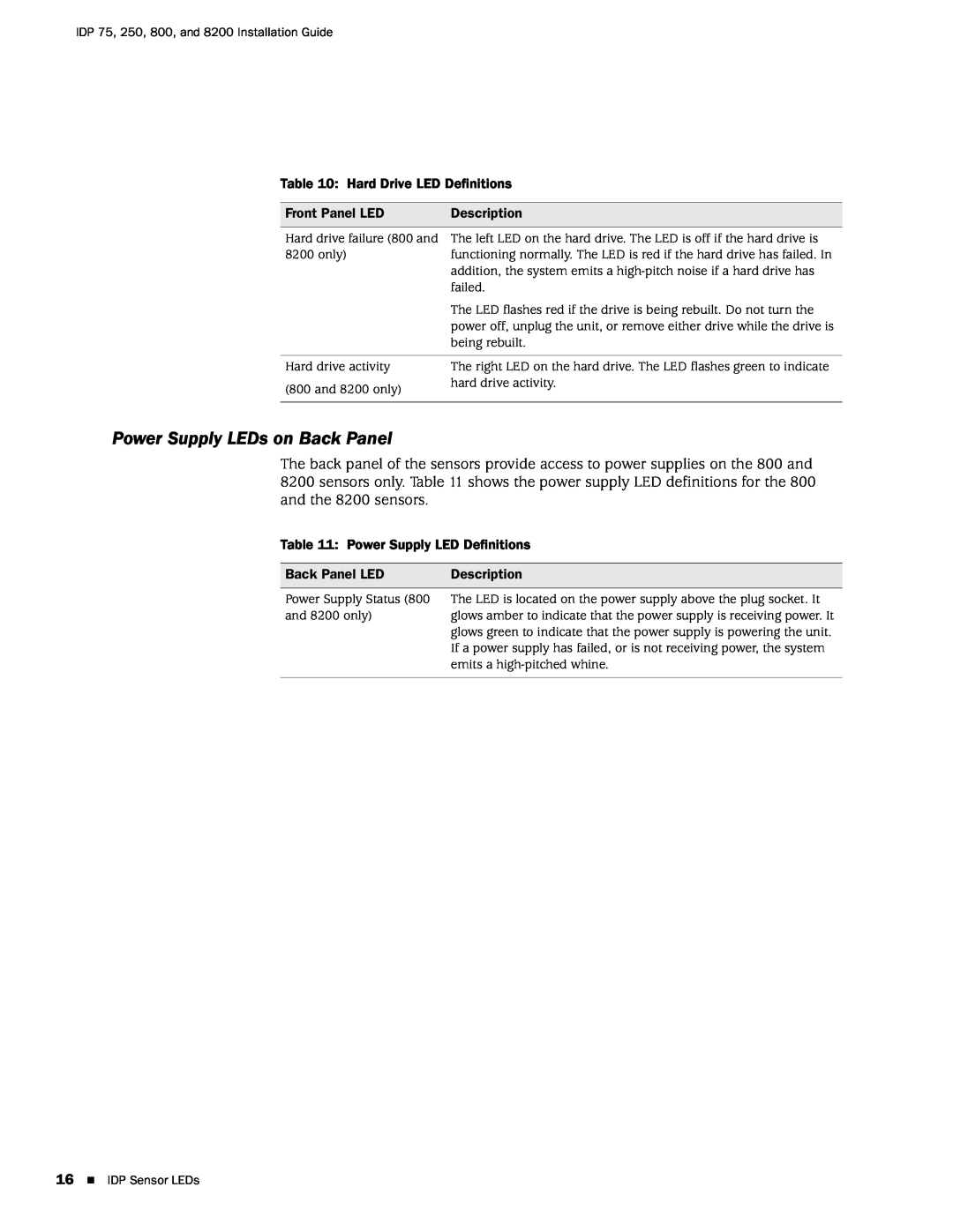
Table 10 Hard Drive LED Definitions
Power Supply LEDs on Back Panel
Table 11 Power Supply LED Definitions
Front Panel LED
Installing the Sensor
General Installation Guidelines
Chapter
Mounting Using Device Rack Rails
Rack Mounting the IDP Sensor
Required Tools
Mounting Using Midmount Brackets
Connecting Power
Simple Configuration
Configuring the IDP Sensor
Initial Configuration Options
Simple Configuration Settings
Simple Configuration Values
Advanced Configuration
Connecting to the Sensor
„9600 bps „8 data bits
Using the Management Port to Configure the Sensor
Connecting Directly Using the Management Port
Connecting Remotely Using the Management Port
Configuration Information
QuickStart Simple Configuration
ACM Advanced Configuration
Configuration Information
Administrator’s Guide
Configuration Information
Manager Administrator’s Guide
Section
Connecting Forwarding Interfaces
Connecting the High Availability Port
Verifying Traffic Flow
Adding Your Sensor to NSM
NetScreen-SecurityManager Installation Guide
Adding the Sensor to NSM
Chapter
b.Select Device is Reachable default
Figure 12 Begin Add Device Procedure
Figure 13 Add Device Wizard - Device Name
6. Enter the following connection information
b.Log in as root
Checking the Status of Your Sensor
Figure 19 Viewing Device Status
IDP 75, 250, 800, and 8200 Installation Guide
34„ Checking the Status of Your Sensor
Updating Software on the Sensor
Loading a Sensor Image into NSM
Chapter
Upgrading Sensor Software
Updating IDP Sensor Software Without NSM
Reimaging the IDP Sensor
IDP 75, 250, 800, and 8200 Installation Guide
38„ Reimaging the IDP Sensor
Servicing the Device
Replacing a Power Supply IDP 800, and 8200 Only
Remove a Power Supply
Chapter
Install a Power Supply
Replacing a Hard Drive IDP 800 and 8200 Only
Remove a Hard Drive
Install a Hard Drive
IDP 75, 250, 800, and 8200 Installation Guide
42„ Replacing a Hard Drive IDP 800 and 8200 Only
Bridge Mode
Advanced Configuration
Advanced Deployment Modes
Chapter
Advantages
IDP 75, 250, 800, and 8200 Installation Guide
Figure 21 Bridge Mode
Disadvantages
Advantages
Router Mode
Figure 22 Router Mode
Disadvantages
Proxy-ARPMode
IDP High Availability Deployment Modes
Specifications
Appendix A
IDP 75 Technical Specifications
IDP 250 Technical Specifications
IDP 800 Technical Specifications
IDP 8200 Technical Specifications
Safety Compliance
EMI Compliance
Immunity
Index
IDP 75, 250, 800, and 8200 Installation Guide
54 „ Index