Model No Serial No GET0467-001A
For customer Use
For safety
Temperature inside the car
Information For U.S.A
Contents
Disc, folder, RPT repeat
Tr track indicator
Display window
Band button
Standby/on/attenuator button
Installing the lithium coin battery CR2025
Do not leave the battery with other metallic materials
For USA-California Only
To drop the volume in a moment ATT
For FM/AM tuner ⁄ Adjust the volume
@ Adjust the sound as you want. See
To turn off the power
Select a desired station frequency
When an FM stereo broadcast is hard to receive
Start searching for a station
To tune in to a station manually
To stop play and eject the disc
Manual presetting
Listening to a preset station
To check other information while listening to the radio
To cancel the prohibition, repeat the same
Prohibiting disc ejection
Skipping tracks quickly during play
Current track
Cancels
Mode Plays at random
Changing the display information
If an iPod has been connected
Adjust the volume Adjust the sound as you want. See
To pause playback
~ Connect an iPod
To check other information while listening to an iPod
Selecting the playback modes
Indication, Range
Finish the procedure Indications Setting, reference
Select a PSM item Adjust the PSM item selected
Subwoofer through an external amplifier
Indications Setting, reference Initial
Adjustment
Speakers through an external amplifier
Moisture condensation
How to clean the connectors
How to handle discs
Adjust the volume ⁄ Adjust the sound as you want. See
To keep discs clean
To play new discs
Tuner operations
Playing a CD-R or CD-RW
Playing an MP3/WMA disc
Disc operations
IPod operations Controllable iPod
Ejecting a disc
English
Disc
Symptoms Remedies/Causes
MP3/WMA playback IPod playback Symptoms Remedies/Causes
AM Tuner
FM Tuner
Call
Lista de piezas para instalación y conexión
Precautions on power supply and speaker connections
Parts list for installation and connection
Liste des pièces pour l’installation et raccordement
Extracción de la unidad Retrait de l’appareil
Installation Montage
Electrical Connections Conexiones Electricas
Troubleshooting
KD-PDR31
Information for Users on Disposal of Old Equipment
Control panel
How to use the M Mode button
Attaching the control panel
Detaching the control panel
Tuner reception indicators-MO monaural, ST stereo
Control dial 0eject button Loading slot
Disp display button ¢ buttons Display window
Skips 10 items at a time if pressed and held
See also General settings PSM on pages 15
Basic operations
Select 24H/12H, then 24H hour or 12H hour
92.5 M
What you can do with RDS
Searching for your favorite FM RDS programme
Frequency ÔClock
Using the standby receptions
TA Standby Reception
PTY Standby Reception
Automatic station selection
PTY codes
Goes off
Same folder
To select a number from 01
Disc RND All tracks of the current disc RND OFF Cancels
While playing an audio CD or a CD Text
Elapsed playing time with the current track number
Enter the main menu
Adjust the volume
~ Connect an iPod
To fast-forward or reverse the track
Random play Mode
Selecting the playback modes
Indication For
BAL balance, L06 to R06
VOL volume, 00 to 30 or 50 *4 Adjust the volume
Codes
Indications Setting, reference
24H/12H
12H
Tag display
Adjustment
Activates dimmer
Phone
Basic operations Turning on the power
FM RDS operations
AUX in ÔClock
Warped, etc
Packet Write method
If you change the AMP Gain setting from
General settings-PSM
English
How to clean the connectors
Do not use the following discs
After starting the heater in the car
Connect the aerial firmly
Skipped You used for recording
Noise is generated
Have intended them to play
On the display
An iPod nano
70 dB
Power Requirement
Temperature Dimensions W × H × D approx
Treble KHz
Having Trouble with operation?
KD-PDR31
Removing the unit
Installation IN-DASH Mounting
Electrical Connections Raccordements Electriques
EN CAS DE Difficultes
Connecting an Apple iPod / Connexion d’un iPod Apple
Руcckий Deutsch English
How to reset your unit
Contents
Playback mode / item indicators-RND random
Skips 10 items at a time if pressed and held
VOL
Radio operations
FM RDS operations
Types
Disc operations
No Eject
IPod operations
If the selected item has another layer, you will
Bass *2 Mid-range *3 Treble *4 Super bass
General settings PSM
English
Dimmer
Tuner operations Storing stations in memory
Playing a CD-R or CD-RW
Ejecting a disc
English
Maintenance
Troubleshooting
Have intended them to play
Specifications
Соответствующую страницу
Затруднения при эксплуатации?
Teileliste für den Einbau und Anschluß
Список деталей для установки и подключения
Предостережения по питанию и подключению громкоговорителей
Removing the unit Ausbau des Geräts Удаление устройства
IN-DASH Mounting IM Armaturenbrett Приборную Панель
Автомобиль оснащен разъемом ISO
Elektrische Anschlüsse
Fehlersuche Bыявление Неисправностей
CD Receiver KD-PDR35
Increase of the output level
Maintenance
Control panel
Equalizer Source button Selects the source
Remote controller RM-RK50
Basic operations ~ Turn on the power
Reception improves, but stereo effect will be lost
Number 4 of the FM1 band
No Eject
Disc RND All tracks of the current disc
IPod operations
To check other information while listening to an iPod
MID
Clock display Turned off
Finish the procedure Indications Setting, reference Initial
When the power is turned off
Display Is done for about 20 seconds
Amplifier gain
Speakers through an external amplifier
Subwoofer through an external amplifier
Frequency
Maintenance
Single CD 8 cm disc
Playing a CD-R or CD-RW
This unit can display up to 40 characters
English
MP3/WMA
MP3/WMA playback IPod playback Symptoms Remedies/Causes
Sensitivity
Distortion
IPod jack
DB Quieting
Having Trouble with operation?
KD-PDR35
√µ‘¥µßÈ- √ª√-Õ·ºßÀπȪ∑¡Ï‡- ¢È
Typical connections / √‡ËÕ¡µËÕ·ªµ
√‡ËÕ¡‚¥¬„ȉøøÈ
Connecting an Apple iPod / √‡ËÕ¡µËÕ- Apple iPod
ΜߧËÈ- L/O Mode ‡ªìπ Rear ¥ŸÀπÈ 15 §·π-π
Instructions Buku Petunjuk
How to reset your unit
Contents
Control panel
Remote controller RM-RK50
Getting started
Radio operations
Number 4 of the FM1 band
No Eject
When TAG Disp is set to TAG OFF
IPod operations
To check other information while listening to an iPod
MID*2 TRE*3
Minute adjustment
Frequency band
Maintenance
More about this unit
Playing a CD-R or CD-RW
IPod with dock connector
English
Troubleshooting
MP3/WMA playback IPod playback Symptoms Remedies/Causes
Impedance Subwoofer-Out
Ada Masalah dengan cara Pengoperasian?
Daftar bagian-bagian untuk pemasangan dan penyambungan
Indonesia
Memindahkan alat penerima
Pemasangan BINGKAI-DALAM Dash
Typical connections / Ciri khas sambungan-sambungan
SAMBUNGAN-SAMBUNGAN Listrik
Buku Petunjuk
Connecting an Apple iPod / Menghubungkan Apple iPod
GET0468-005A
How to reset your unit
Contents
Control panel
Remote controller RM-RK50
Getting started
Radio operations
Disc operations
No Eject
Disc RND All tracks of the current disc
IPod operations
To check other information while listening to an iPod
MID
General settings PSM
SCROLL*2 Once
Maintenance
More about this unit
Playing a CD-R or CD-RW
Ejecting a disc
English
Troubleshooting
MP3/WMA playback IPod playback Symptoms Remedies/Causes
Specifications
EN, CT
安裝/連接手冊
安裝(裝設、固定在儀表板內)
When using the optional stay / 若選用支撐架
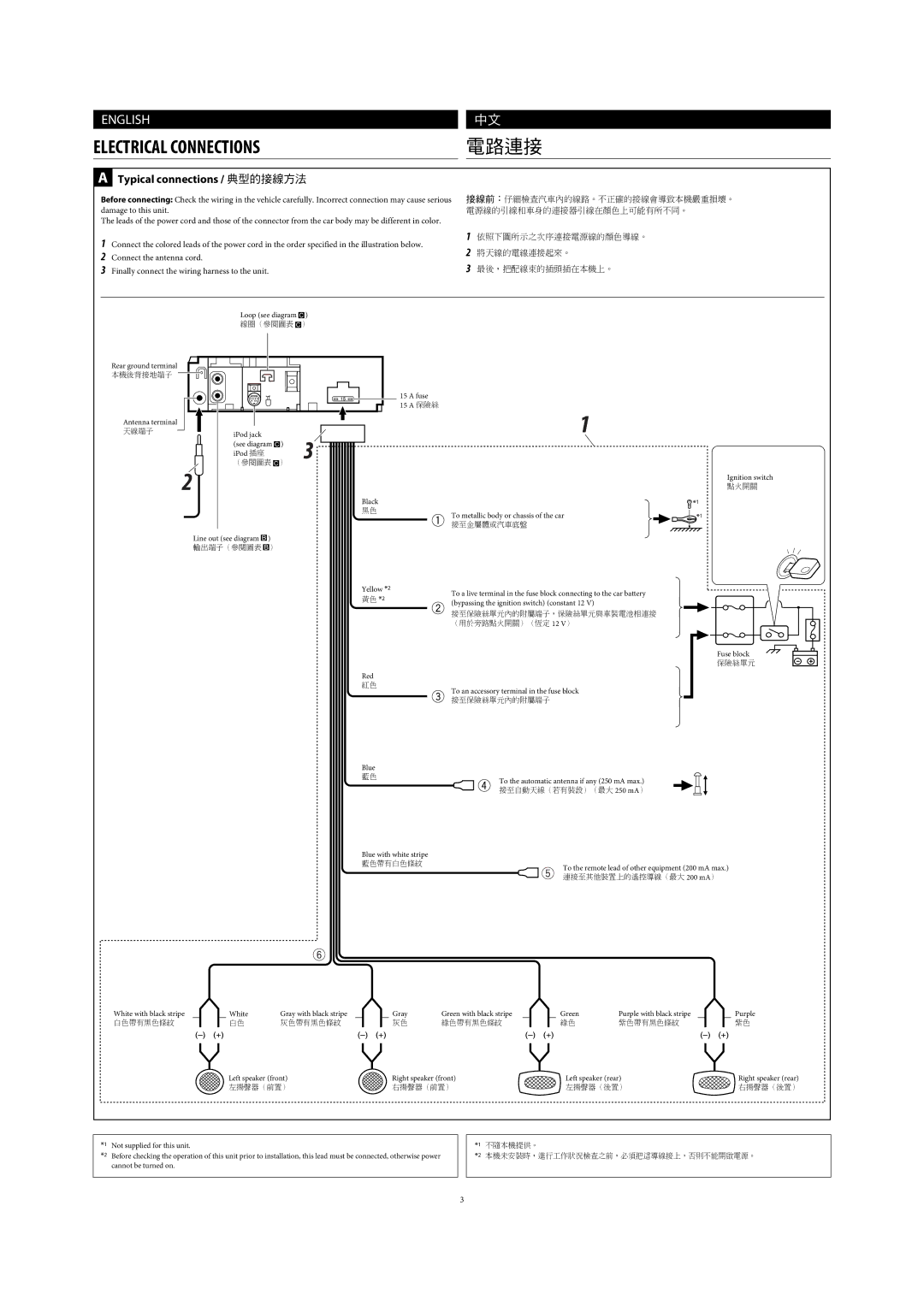
Typical connections / 典型的接線方法
Electrical Connections
將L/O MODE設定為WOOFER(參閱使用 說明書的第15 頁。)
Connecting an Apple iPod / 連接 Apple iPod