For customer Use
For canceling the display demonstration, see
Model No Serial No GET0576-001A
Temperature inside the car
For safety
Information For U.S.A
Contents
Basic operations
Display window
Before using the remote controller
Using the remote controller RM-RK50
Cancel the display demonstrations
Turn on the power
Preparation
Set the clock
Listening to the radio
You can preset up to 18 stations for FM
Select FM or AM
Station Sequential Memory
Prohibiting disc ejection
Disc operations
Selecting a track/folder
Selecting the playback modes
Listening to the USB device
Repeat Ô Random
ALL RND
Straightly pull it out from the unit
Listening to the other external components
Do not start the car engine if a USB device is connected
For more details about USB operations, see pages 19
Preset value setting for each sound mode
Selecting a preset sound mode
To erase the entire title
Title assignment
Menu operations
Area EU
Area Area US
Area SA
If Band Auto
Rear
Mode SUB.W
LOW
MID
Adjust the level 00 to 31 of the selected primary color
Color settings
Creating your own color -USER Color
Select Color = User
More about this unit
Bit rate of MP3 32 kbps 320 kbps Sampling frequency of MP3
Playing an MP3/WMA disc
Romeo up to 64 characters Joliet up to 32 characters
Search function works but search speed is not constant
This unit does not support SD card reader
Ejecting a disc or removing a USB device
Symptoms Remedies/Causes
Troubleshooting
Playback
USB device playback Symptoms Remedies/Causes
How to clean the connectors
Maintenance
Do not use the following discs
Audio Amplifier Section
Specifications
≤ 1% THD+N
USB Section
CD Player Section
General
Call
KD-R400
Installation
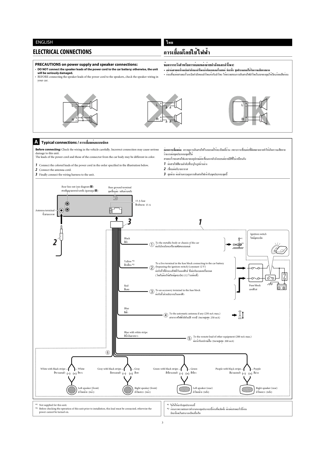
Precautions sur l’alimentation et la connexion des enceintes
Precautions on power supply and speaker connections
Troubleshooting
KD-R501/KD-R402/KD-R401
European Union only
Battery Products
Components Using the remote controller-RM-RK50
Enter PTY Searching mode Hold
Confirm the selection Press FM Enter SSM preset mode Hold
FM = CD * 2 = USB = AUX in * 3 = AM * 3 =
MO monaural Disc Folder, RPT repeat EQ equalizer indicator
Station Frequency = Clock = back to the beginning
Procedure. To return to the previous menu, press Back
FM Radio
Beginning
Automatic presetting FM-SSM Strong
Ex. Storing FM station of 92.50 MHz into preset number
Manual presetting FM/AM
TA Standby Reception
Appears
To activate TA Standby Reception
PTY codes
PTY Standby Reception
MP3/WMA Select folder PressSelect track
Turn on the power Insert a disc
PressPause/resume playback
Hold Reverse/fast-forward track
Press SRC to listen to another playback source
To stop play and detach the USB device
Adjust the sound as you want see pages 14
Adjust the volume
Select AUX
Installing the lithium coin battery CR2025
Using the remote controller RM-RK50
Turns the power on if pressed briefly or
See page 15 for User settings
Select User for EQ
Storing your own sound mode
Repeat if necessary
Select the desired item
24H/12H
Hour
AF on
Volume
Mono on
BALANCE*8
FADER*7,*8 R06 F06
Loud Loud OFF
Muting
AM*11
Color settings for KD-R501
AUX IN*12
Select a primary color
FM Radio Data System operations
Pickup lens inside the unit is dirty
Use only finalized CD-Rs or CD-RWs
This unit cannot play back the following files
On the display
Connect the aerial firmly
Compliant with ISO 9660 Level 1, Level 2, Romeo, or
Album name
Numbers, and a limited number of symbols
Make sure to store discs in cases after use
New discs may have some rough spots
Per channel
Maximum Power Output
Distortion
70 dB
0C to +40C
Power Requirement Operating Voltage
Ανατρέξτε στην ενότητα Επαναφορά της µονάδας
Соответствующую страницу
Anschließen der Stromversorgung
Precautions on power supply and speaker connections
Κατάλoγoς εξαρτηµάτων για την εγκατάσταση και τις συνδέσεις
Πρoφυλαξεισ κατά τις συνδέσεις
Einbau
Электрические Подключения Ηλεκτρικεσ ΣΥΝ∆ΕΣΕΙΣ
Λευκή ρίγα µε τo καλώδιo τηλεχειρισµoύ της
Bыявление Неисправностей
KD-R407
For canceling the display demonstration, see
Available characters Display indications
Available characters on the display
Selecting a preset sound mode Menu operations
Select the source AUX auxiliary input jack
Turn off the power Hold
Operations
Station Frequency =Clock =back to the beginning
Select Clock =CLOCK SET
To the beginning
Turn =Press
Search for a station to listen-Auto Search
Select FM, AM, or FM-LO
FM-LO 65.00 MHz 74.00 MHz
SSM
Number
FM-LO, and 6 stations for AM
Tracing the same programme- Network-Tracking Reception
Selecting the playback modes
RPT OFF or RND OFF
To cancel repeat play or random play, select
Randomly plays all tracks
Adjust the sound as you want see pages 13
Freq
See page 14 for User settings
Adjustment made will be stored automatically
Scroll
Demo
Initial
Search *4
AF-REG *4 AF on
MONO*6 Mono on
FADER*7, *8 R06 F06
AMP GAIN*10
TEL Muting
AUX IN*12 AUX OFF
More about this unit
Windows extension up to 32 characters
Menu operations
Discs
Number of symbols see
To remove these rough spots, rub the edges with a
MHz to 74.00 MHZ
Maximum Power Output Front/Rear Per channel
KHz to 1 620 kHz
KHz to 279 kHz
English References
Для получения информации о перезагрузке Вашего устройства
Затруднения при эксплуатации?
Застереження щодо приєднання джерела
Precautions on power supply and speaker
Перелік деталей для встановлення та з’єднання
Встановлення
Електричні З’ЄДНАННЯ
Несправності
KD-R504
Do not raise the volume level too much, as this will
Contents
Select the sound mode
Enter list operations Enter Menu setting Hold
Select the source Remote sensor
FM = AM*2 = CD*3 = USB = AUX IN*2 =
Operations
Time
Preparation
Select FM or AM Search for a station to listen-Auto Search
For AM
Selecting preset station
PressPause/resume playback
Adjust the volume Adjust the sound as you want see pages 12
Selecting a preset sound mode
Title assignment
MONO*3 Mono on
Monaural mode
BALANCE*5
FADER*4,*5 R06 F06
Initial VOL
ADJ Source
AM station
AUX
MP3 files encoded in an inappropriate format
Ink jet printer
Title assignment
General
Discs in general MP3/WMA playback Symptoms Remedies/Causes
Have intended them to play Recorded
New discs may have some rough spots
AM Tuner Sensitivity 20 μV Selectivity 35 dB
CD Player Section
Having Trouble with operation?
KD-R504
When installing the unit without using the sleeve
Electrical Connections
KD-R506/KD-R505/ KD-RC502/KD-RC501
Do not raise the volume level too much, as this will
Contents
Basic operations
Operations
Using the remote controller RM-RK50
Preparation
Listening to the radio
Disc operations
Listening to the USB device
For more details about USB operations, see
Level
Title assignment
Menu operations
If Band Auto
AUX IN*9
WMA files which are not based upon Windows Media Audio
Title assignment
Troubleshooting
Numbers, and a limited number of symbols
Maintenance
Specifications
English References
EN, TH
KD-R506/KD-R505/KD-RC502/KD-RC501
√µ‘¥µ-Èß√ª√-Õ·ºßÀπȪí∑¡Ï‡¢È
√‡ËÕ¡‚¥¬„ȉøøÈ
√µ√« Õªí≠À¢-¥¢ÈÕß