50 EN | USING MENUS FOR DETAILED ADJUSTMENT (cont.) |
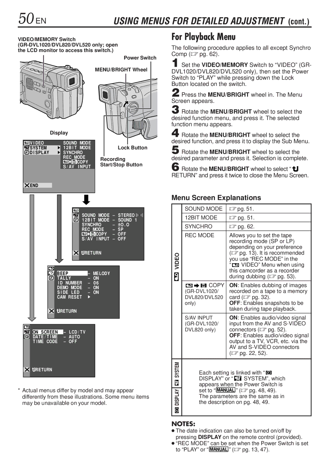
VIDEO/MEMORY Switch
Power Switch
MENU/BRIGHT Wheel |
|
| Display |
|
|
|
|
|
|
|
|
|
|
|
|
|
|
|
|
|
|
|
|
| |||||
|
|
|
|
|
|
|
|
|
|
|
|
|
|
|
|
|
|
|
|
|
|
| ||||||
|
|
|
|
| SOUND MODE |
|
|
|
|
|
|
|
|
|
|
|
| |||||||||||
| V I DEO |
|
|
|
|
|
|
|
|
|
|
|
|
|
| |||||||||||||
| SYSTEM |
|
| 1 2B I T MODE |
|
|
|
| Lock Button | |||||||||||||||||||
| D I SPLAY |
|
| SYNCHRO |
|
|
|
|
|
|
|
|
|
|
|
|
|
| ||||||||||
|
|
|
|
|
| REC MODE |
|
|
| Recording | ||||||||||||||||||
|
|
|
|
|
|
|
|
|
|
|
| COPY |
|
|
| |||||||||||||
|
|
|
|
|
|
|
|
|
|
|
|
|
|
| Start/Stop Button | |||||||||||||
|
|
|
|
|
| S / AV I NPUT |
| |||||||||||||||||||||
|
|
|
|
|
|
|
|
|
|
|
|
|
|
|
|
|
| |||||||||||
|
|
|
|
|
|
|
|
|
|
|
|
|
|
|
|
|
|
|
|
|
|
|
|
|
| |||
| END |
|
|
|
|
|
|
|
|
|
|
|
|
|
|
|
|
|
|
|
|
|
|
| ||||
|
|
|
|
|
|
|
|
|
|
|
|
|
| SOUND MODE – STEREO |
|
|
|
| ||||||||||
|
|
|
|
|
|
|
|
|
|
|
|
|
|
|
|
|
| |||||||||||
|
|
|
|
|
|
|
|
|
|
|
|
|
|
|
|
|
| |||||||||||
|
|
|
|
|
|
|
|
|
|
|
|
|
|
|
|
|
| |||||||||||
|
|
|
|
|
|
|
|
|
|
|
|
|
| 1 2B I T MODE | – | SOUND 1 | ||||||||||||
|
|
|
|
|
|
|
|
|
|
|
|
|
| SYNCHRO | – |
| O . O | |||||||||||
|
|
|
|
|
|
|
|
|
|
|
|
|
|
| ||||||||||||||
|
|
|
|
|
|
|
|
|
|
|
|
|
| REC MODE | – | SP | ||||||||||||
|
|
|
|
|
|
|
|
|
|
|
|
|
|
|
|
|
| COPY | – | OF F | ||||||||
|
|
|
|
|
|
|
|
|
|
|
|
|
|
|
| I NPUT | – | OF F | ||||||||||
|
|
|
|
|
|
|
|
|
|
|
|
| S / AV |
| ||||||||||||||
|
|
|
|
|
|
|
|
|
|
|
|
|
| RETURN |
|
|
|
|
|
|
|
|
| |||||
|
|
|
|
|
|
|
|
|
|
|
|
|
| – | MELODY |
|
|
|
|
|
|
|
|
| ||||
|
|
|
|
|
|
|
|
|
|
|
|
|
|
|
|
|
|
|
|
|
|
|
| |||||
|
|
|
| BEEP |
|
|
|
|
|
|
|
|
|
|
|
|
|
|
|
| ||||||||
|
|
|
| TAL LY |
| – | ON |
|
|
|
|
|
|
|
|
| ||||||||||||
|
|
|
| I D |
| NUMBER |
| – | 0 6 |
|
|
|
|
|
|
|
|
|
| |||||||||
|
|
|
| DEMO MODE | – | ON |
|
|
|
|
|
|
|
|
| |||||||||||||
|
|
|
| S I DE | LED | – | ON |
|
|
|
|
|
|
|
|
| ||||||||||||
|
|
|
| CAM RESET |
|
|
|
|
|
|
|
|
|
|
|
|
|
| ||||||||||
|
|
|
|
|
|
|
|
|
|
|
|
|
|
|
|
|
|
|
|
|
|
|
|
|
|
| ||
|
|
|
| RETURN |
|
|
|
|
|
|
|
|
|
|
|
|
|
| ||||||||||
|
|
|
|
|
|
| – | LCD / TV |
|
|
|
|
|
|
|
|
|
|
|
|
|
| ||||||
|
|
|
|
|
|
|
|
|
|
|
|
|
|
|
|
|
|
|
|
| ||||||||
| ON SCREEN |
|
|
|
|
|
|
|
|
|
|
|
|
|
|
|
|
| ||||||||||
| DATE / T I ME |
|
|
| – | AUTO |
|
|
|
|
|
|
|
|
|
|
|
|
|
| ||||||||
| T I ME CODE |
|
|
| – | OF F |
|
|
|
|
|
|
|
|
|
|
|
|
|
| ||||||||
![]()
![]() RETURN
RETURN
*Actual menus differ by model and may appear differently from these illustrations. Some menu items may be unavailable on your model.
For Playback Menu
The following procedure applies to all except Synchro Comp (☞ pg. 62).
1 Set the VIDEO/MEMORY Switch to “VIDEO” (GR- DVL1020/DVL820/DVL520 only), then set the Power Switch to “PLAY” while pressing down the Lock Button located on the switch.
2 Press the MENU/BRIGHT wheel in. The Menu Screen appears.
3 Rotate the MENU/BRIGHT wheel to select the desired function menu, and press it. The selected function menu appears.
4 Rotate the MENU/BRIGHT wheel to select the desired function, and press it to display the Sub Menu.
5 Rotate the MENU/BRIGHT wheel to select the desired parameter and press it. Selection is complete.
6 Rotate the MENU/BRIGHT wheel to select “ ![]()
![]()
![]()
![]()
![]()
![]()
![]() RETURN” and press it twice to close the Menu Screen.
RETURN” and press it twice to close the Menu Screen.
Menu Screen Explanations
|
|
| SOUND MODE | ☞ pg. 51. | |||||||||||
|
|
| 12BIT MODE | ☞ pg. 51. | |||||||||||
|
|
| SYNCHRO |
| ☞ pg. 62. | ||||||||||
|
|
| REC MODE |
| Allows you to set the tape | ||||||||||
|
|
|
|
|
|
|
|
| recording mode (SP or LP) | ||||||
|
|
|
|
|
|
|
|
| depending on your preference | ||||||
| VIDEO |
|
|
|
|
|
| (☞ pg. 13). It is recommended | |||||||
|
|
|
|
|
|
| you use “REC MODE” in the | ||||||||
|
|
|
|
|
|
|
|
| “ |
|
| VIDEO” Menu when using | |||
|
|
|
|
|
|
|
|
|
|
| |||||
|
|
|
|
|
|
|
|
| this camcorder as a recorder | ||||||
|
|
|
|
|
|
|
|
| during dubbing (☞ pg. 53). | ||||||
|
|
|
|
|
|
| COPY | ON: Enables dubbing of images | |||||||
|
|
|
|
|
|
| |||||||||
|
|
| recorded on a tape to a memory | ||||||||||||
|
|
| DVL820/DVL520 | card (☞ pg. 32). | |||||||||||
|
|
| only) |
| OFF: Enables snapshots to be | ||||||||||
|
|
|
|
|
|
|
|
| taken during tape playback. | ||||||
|
|
| S/AV INPUT |
| ON: Enables audio/video signal | ||||||||||
|
|
| input from the AV and | ||||||||||||
|
|
| DVL820 only) |
| connectors (☞ pg. 52). | ||||||||||
|
|
|
|
|
|
|
|
| OFF: Enables audio/video signal | ||||||
|
|
|
|
|
|
|
|
| output to a TV, VCR, etc. via the | ||||||
|
|
|
|
|
|
|
|
| AV and | ||||||
|
|
|
|
|
|
|
|
| (☞ pg. 22, 52). | ||||||
|
|
|
|
|
|
|
|
|
|
|
|
|
|
|
|
SYSTEM |
|
| Each setting is linked with “ |
|
| ||||||||||
|
|
|
|
|
|
| |||||||||
|
|
|
|
| DISPLAY” or “ |
|
| SYSTEM”, which | |||||||
|
|
|
|
|
|
| |||||||||
|
|
|
|
| appears when the Power Switch is | ||||||||||
DISPLAY |
|
| set to “ | MANUAL | ” (☞ pg. 48, 49). | ||||||||||
|
|
|
|
| |||||||||||
|
| the description on pg. 48, 49. | |||||||||||||
|
|
|
|
| The parameters are the same as in | ||||||||||
|
|
|
|
|
|
|
|
|
|
|
|
|
|
|
|
|
|
|
|
|
|
|
|
|
|
|
|
|
|
|
|
|
|
|
|
|
|
|
|
|
|
|
|
|
|
|
|
NOTES:
●The date indication can also be turned on/off by pressing DISPLAY on the remote control (provided).
●“REC MODE” can be set when the Power Switch is set
to “PLAY” or “ | MANUAL | ” (☞ pg. 13, 47). |