58 EN | CONNECTIONS Basic Connections |
These are some basic types of connections. When making the connections, refer also to your VCR and TV instruction manuals.
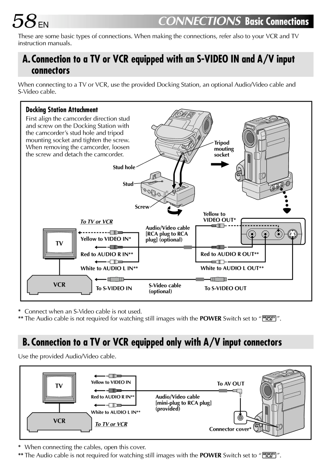
A. Connection to a TV or VCR equipped with an
When connecting to a TV or VCR, use the provided Docking Station, an optional Audio/Video cable and
Docking Station Attachment |
| |
First align the camcorder direction stud |
| |
and screw on the Docking Station with |
| |
the camcorder’s stud hole and tripod |
| |
mounting socket and tighten the screw. | Tripod | |
When removing the camcorder, loosen | ||
mouting | ||
the screw and detach the camcorder. | socket | |
Stud hole |
| |
Stud |
| |
Screw |
|
TV |
| Yellow to | |
To TV or VCR | VIDEO OUT* | |
Audio/Video cable | ||
| ||
Yellow to VIDEO IN* | [RCA plug to RCA | |
plug] (optional) | ||
Red to AUDIO R IN** | Red to AUDIO R OUT** |
|
|
|
|
|
|
|
|
|
|
|
|
|
|
|
|
|
|
|
|
|
|
|
| |
|
| White to AUDIO L IN** |
| White to AUDIO L OUT** | ||||||||||||||||||||
|
|
|
|
|
|
|
|
|
|
|
|
|
|
|
|
|
|
|
|
|
|
|
| |
VCR |
|
|
|
|
|
|
|
|
|
|
|
|
|
|
|
|
|
|
|
|
| |||
To | To | |||||||||||||||||||||||
|
| (optional) | ||||||||||||||||||||||
|
|
|
|
|
|
|
|
|
|
|
|
|
|
|
|
|
|
|
|
|
|
| ||
*Connect when an S-Video cable is not used.
**The Audio cable is not required for watching still images with the POWER Switch set to “
MEMORY PLAY
”.
B. Connection to a TV or VCR equipped only with A/V input connectors
Use the provided Audio/Video cable.
TV |
VCR
Yellow to VIDEO IN | To AV OUT |
Red to AUDIO R IN** | Audio/Video cable |
| |
White to AUDIO L IN** | (provided) |
|
To TV or VCR
Connector cover*
*When connecting the cables, open this cover.
**The Audio cable is not required for watching still images with the POWER Switch set to “
MEMORY PLAY
”.