6. SETTING AND ADJUSTMENTS BEFORE SHOOTING
7. SHOOTING OPERATION
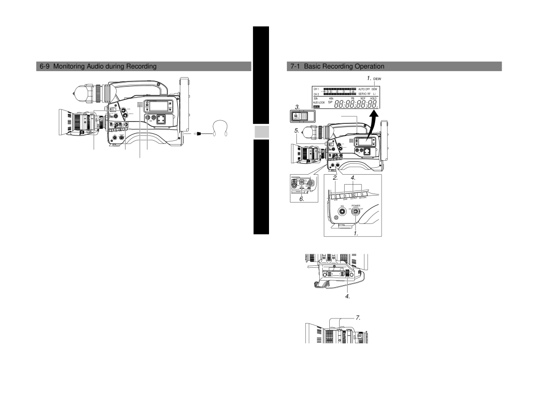
6-9 Monitoring Audio during Recording
|
|
|
|
|
| OPERATE/WARNING |
|
|
|
|
|
|
|
| LIGHT |
|
|
|
|
|
| RESET |
|
|
|
|
|
|
| MONITOR | COUNTER |
|
| FILTER |
|
| SELECT | ||
| 1 3200k |
|
| ALARM |
|
| |
| 2 | 5600k |
|
|
|
|
|
| 3 5600k+ND |
|
|
|
| ||
| SHUTTER | STATUS |
| MONITOR |
|
| |
| MENU |
|
|
|
|
| |
|
|
|
|
|
|
| |
|
|
|
|
|
| LEVEL |
|
| VTR | GAIN | OUTPUT | WHT.BAL |
|
| |
|
|
|
|
| |||
|
|
| NG | POWER |
|
| |
|
|
|
| ON | OFF |
|
|
|
|
|
|
|
|
| EARPHONE |
|
|
|
|
|
|
| jack |
ALARM | MONITOR | MONITOR SELECT | |||||
control | control |
| switch |
| |||
|
|
|
|
|
| Monitoring |
|
|
|
|
|
|
| loudspeaker |
|
The audio input during recording, in
•The monitoring audio is not output from the loudspeaker while the EARPHONE jack is in use.
•Select the audio channel to be monitored using the MONITOR SELECT switch.
MIX : The sound input to the CH1 and CH2 channels is output mixed.
•The MONITOR volume control adjusts the monitoring volume.
•The loudspeaker or earphone outputs an alarm tone in the case of an abnormal condition occurring in the unit.
An alarm tone is also output when the tape end is reached or when the battery is running down. The alarm tone volume can be adjusted with the ALARM control. For details on the alarm tone, see page 87.
*Do not increase the audio monitoring volume excessively; otherwise howling with the camera microphone may occur.
7-1 Basic Recording Operation
1. “DEW”
| CH 1 |
|
|
|
|
| OVER | AUTO OFF |
| DEW | |
|
| 40 30 |
| 20 |
| 10 | 0 dB | SERVO RF | L i | ||
| CH 2 |
|
|
|
|
| OVER | ||||
| 32k | 48k |
|
|
| PB | NDF | HOLD | |||
3. | AUD LOCK | SP |
|
|
|
|
|
|
|
|
|
MENU |
|
|
|
| H |
| M | S |
| F | |
EJECT | Eject switch |
|
|
|
|
|
| ||||
|
|
|
|
|
|
|
|
|
|
| |
5. |
|
|
|
|
|
|
|
|
|
|
|
|
| FILTER |
|
|
|
|
|
|
|
|
|
|
|
|
|
|
| ALARM |
|
|
|
|
|
|
|
|
|
|
| MONITOR |
|
|
|
|
|
|
|
| GAIN | OUTPUT | WHT.BAL |
|
|
|
|
| |
|
| VTR |
|
|
|
|
|
|
| ||
|
| NG | POWER |
|
|
|
|
|
| ||
SKIN | AUTO |
| 2. |
|
| 4. |
|
|
| ||
OFF ZEBRA |
|
|
|
|
|
|
|
|
|
|
|
AREA | WHITE |
|
|
|
|
|
|
|
|
|
|
| ACCU |
|
|
|
|
|
|
|
|
|
|
| FOCUS |
|
|
|
|
|
|
|
|
|
|
VTR AUDIO | TAKE |
|
|
|
|
|
|
|
|
|
|
LEVEL |
|
|
|
|
|
|
|
|
|
| |
|
|
|
|
|
|
|
| E | B |
|
|
|
|
|
|
|
| L | MA | NO EN | AT |
|
|
|
|
|
| Y |
| C | FKO | SR |
|
| |
6. |
|
| BT |
| M | SR | FOTU | P |
|
| |
|
| SE |
| H | BA | A | WHT.BAL |
|
| ||
| VTR |
|
|
|
|
|
| ||||
|
|
|
| S |
|
|
|
|
|
| |
|
|
|
| VA |
|
| OUTPUT |
|
|
| |
|
|
|
|
|
| GAIN |
|
|
|
|
|
|
|
|
|
|
| NG | POWER |
|
| ||
|
|
|
|
|
|
| ON |
| OFF |
|
|
1.
RET | M |
| A |
W T
4.
1. Set the POWER switch to ON.
Power is supplied to the unit.
Check that the condensation indicator "DEW" does not appear on the display. If it is lit, wait until the indicator goes out.
2. Set the VTR switch to the STBY position.
Even when the VTR switch is set to the "SAVE" position, pressing the VTR trigger button will start recording. However, in this case, it is necessary to wait a short time until the recording actually starts.
For details on the VCR SAVE mode, see page 52.
3. Slide the EJECT switch to open the cassette cover.
•Ensure that the switch on the back of the videocassette is set to REC and insert the cassette correctly.
When the cassette is inserted, the tape is loaded and the unit enters the
•Slowly close the cassette cover.
•Use a videocassette marked MiniDV.
•If the cassette cover is not closed, the
•At the loading time and power switch set to on time, the
•After the cassette cover is closed, it takes about 8 seconds before the unit is ready for recording.
4.Set the switches as required.
• GAIN | : Sensitivity suitable for the subject |
•OUTPUT : "CAM/AUTO KNEE ON"
•WHT-BAL : "A" or "B"
•Set the IRIS switch of the lens to "A".
5.Select the FILTER according to the lighting condition. Position 1 (3200K) : For shooting indoors or outdoors when
illumination is not sufficient
Position 2 (5600K) : For shooting outdoors Position 3 (5600K + ND):
For shooting outdoors under a clear sky.
6. Adjust the white balance.
☞ See "White Balance Adjustment" on page 45.
7.Point the camera at the subject and determine the angle of view and focus with the zoom lever and the focusing ring.
7.
MACRO
4950