HM-DR10000EU
Safety Precautions
MTP PAL
Symptoms of dirty video heads
Early symptom
Late symptom Block noise Still image
Do not place the recorder
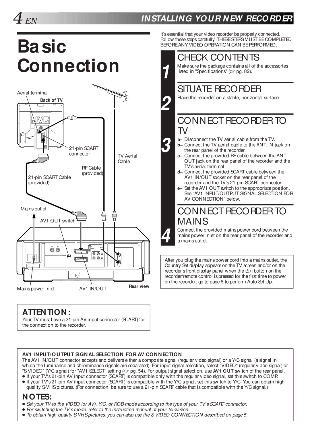
Check Contents
Basic Connection
Situate Recorder
Mains
Video Connection
Connect Recorder to TV
Connect Recorder to Mains
Back of Recorder
If you are referring to the front display panel
Auto Set Up
If you are referring to the on-screen display
Language Code
Preset Download
Press %Þ to select CH - and press OK or #
Press %Þ to move Highlight bar pointer to
Link and press OK
If both auto channel set and auto clock set have failed
Language for the on-screen display
Just Clock
Just Clock on
Language
Screen
ENABLE/DISABLE ON-SCREEN Display
On-Screen Displays
Power Save Mode
Select Power Save
Mode
Return to Normal Screen
Access Mode SET Screen
Access Main Menu Screen
Link Functions
Colour System Set
Return to Normal Screen
About Ntsc Playback
Press %Þ to move the highlight bar pointer to
Basic Playback
Load a Cassette
Point
Start Playback
Playback Features
Pause During Playback
Still Picture/Frame-By-Frame Playback
Press Pause
Adjust Tracking
Activate HIGH-SPEED Search
Override Automatic Tracking
Manually
Activate Index Search
Index Search
Digital TBC/NR S-VHS/VHS Mode Only
Digital 3R S-VHS/VHS Mode Only
Repeat Playback
Soundtrack Selection D-VHS Mode
Soundtrack Selection S-VHS/VHS Mode
During Playback
Basic Recording
Compatibility Of Cassettes And Recording Mode
Recording Mode
Recording Features
Engage ITR Mode
Select Channel to Watch
Start Recording
Reset Counter
SET Counter Display
Display Remaining Time
Elapsed Recording Time Indication
VHS Super VHS And VHS
Receiving Stereo And Bilingual Programmes
Audio Rec Mode Setting D-VHS Mode Only
To Record Stereo And Bilingual Programmes A2
Select B.E.S.T. Mode
S.T. Picture
Preparation
S.T., then press OK or
Playback
Recording
Or press Record on the recorder
Timer Programming
VHS or VHS mode
VHS mode Press STD/LS3
Satellite Tuner Users
Start Time
Express Timer Programming
Time
SET VPS/PDC Mode
Timer Mode
SET Tape Speed
Engage RECORDER’S
Check, Cancel And Replace Programmes
Press ä or äTIMER
Press Again to check More information. Each
Time you press
Auto SP→LP Timer S-VHS/VHS Mode Only
For Example
SET, then press OK or #
Then press OK or #to select
Auto Timer
Highlight bar pointer to Mode SET, then press
Auto TIMER, then press
OK or #to select either
Prog REC Mode
Automatic Satellite Programme Recording
SET Tape Speed
Before performing the following steps
Access Title Screen
Navigation
Load a Recorded Cassette
Choose a Programme
Access Main Menu Screen
Access Video Navigation Screen
Check Memory
Turn OFF Navigation
Title Editing
Access Video
Edit Tape Title
Enter Character
Enter Character
Select Category
Entering Character
Delete Tape Data
Select Tape Title
Delete Tape Data
Delete Programme
Data
Delete Programme Data
To delete, then press
Access Sorting Screen
Sorting By Tape Number
Sorting By Date
Sorting By Category
Remote Control Functions
SET Remote Control
Remote A/B Code Switching
Code
TV Multi-brand Remote Control
TV/VCR, TV +/- Volume
SET TV Brand Code
Operate TV
Satellite Tuner Multi-Brand Remote Control
SET Satellite Tuner
Brand Code
TV Prog +/-,NUMBER keys
Access Mode SET
Control SET Mode
Preparation For Editing
Select Picture
Edit From Camcorder
DV Sound Setting
If the camcorder has an S-VIDEO output connector
If the camcorder has a DV OUT connector Recorder
Recorder
Edit To Or From Another Video Recorder
Recorder Player
AV1 Select Setting
AV2 Select Setting
Synchro Editing
Synchro Edit connector Lanc Cable not provided
Repeat steps 5 7 as necessary
Access Initial SET Screen
Access Jlip ID NO. SET Screen
Terminal Jlip Joint Level Interface Protocol Connector
SET Jlip ID Number
Connection To Satellite Tuner
Simple Connections
Satellite Tuner Unit
Back of TV
Perfect Connections
Connectors Scart
Decoder
Basic Connections
Cable
Connecting Using a Decoder
Select Input Mode
Connect Decoder
SET Tuner
Connecting Using a Stereo System
Rear View
Tuner Set
Access Auto CH SET
Auto Channel Set
Perform Auto Channel SET
View Confirmation Screen
Access Main Menu
Access Confirmation Screen
Select Band
Input Channel
When Receiving a Scrambled Broadcast
Delete a Channel
Change Station Channel Position
Press %Þ @ #until the item you want to move begins
Enter NEW Character
TV Station And ID List
Access Manual Channel SET Screen
Perform Tuning
Fine-Tuning Channels Already Stored
Select Channel to FINE-TUNE
Showview Setup
Number
Enter Receiving Channel Position Number
Guide Program Number Set
Access Initial SET Screen
Access Clock SET Screen
Clock Set
Turn the Recorder on
Default setting is OFF. Set as desired by pressing
Recorder is preset to receive clock setting
SET Just Clock
Channel position to the number representing
Remote control wont function
No power is applied to the recorder
Press Play to turn the indicator off Check the cassette
Timer Recording
Error Code
Ä remain lit on the display panel. Is there Problem?
Quest Ions and Answers
Pull the front panel to access covered buttons/connectors
Index
Inside View of Front Panel
Rear View
Display does not show the -2 of -200000. In this
If the counter exceeds -20 hours -200000,
Case, confirm the counter on the TV screen
80 EN
Remote Control LCD
Recording specification
PAL-type colour signal and Ccir
Express Timer Programming
Manual Channel Setting Manual Tracking
Automatic Satellite Programme Recording
Change Station Channel Position
Ex. Francais is selected for Belgium
Ex. Deutschland is selected
International Telephone Language Code